
Electric Vehicle 2016
Written 10-8-19
Coming in from rotation during the SciOly 2016 season was Electric Vehicle. The task sounded simple enough. Have an electric powered vehicle travel as fast as possible and stop at a certain distance. With relatively little experience around my belt, this project proved a daunting but very rewarding experience.
v1
Being the clueless sophomore I was, I started out completely focused on accuracy. I really didn’t know anything about proper mechanical design or what factors to consider. The most precise motor is generally a stepper motor, so I started with that. I threw 4 of them onto an MDF baseplate along with an Arduino Mega and some stepper drivers. Here’s the result:
I remember bringing v1 to Troy to do some testing. It was decently accurate, but far from enough to account for its slowness. Mr. Wahl even commented on how slow it was. It was pretty clear that I needed something much faster.
v2
With not too much time left before tryouts, I immediately got to work on v2. I completely scrapped the stepper motor idea. After much research on the fastest hobbyist electric cars, I settled on working off of a 1:10 RC car. It took a bit of looking around but I found one for about $150 from a local hobby shop. Just driving it around I could feel how many orders of magnitude faster it was compared to stepper motors.
Next up was restricting the car to drive straight and throw on some kind of breaking system. Since I didn’t want to modify the car too much, I cut up a piece of acrylic and screwed it on in place of the steering. I then attached some wheels and a wing nut onto a 5/16″ threaded rod. Steering was pretty hard to get straight with the standard rear wheel drive, so I flipped it around to use front wheel drive.
The electronics were really straightforward. I just used an Arduino Uno to turn the motor on and off. It didn’t have to handle any braking since I was using a purely mechanical wing nut brake. I just added a sensor near the end of the wing nut’s travel to tell the Arduino to turn off the motor. For aiming, I added a laser pointer.
I don’t really have any photos, but here’s some videos:
I used v2 at tryouts. One thing I didn’t account for was that the floors in the science building were notoriously dirty. v2 ended up being fast, but not accurate. Still, it was the best of the bunch and got me on the team.
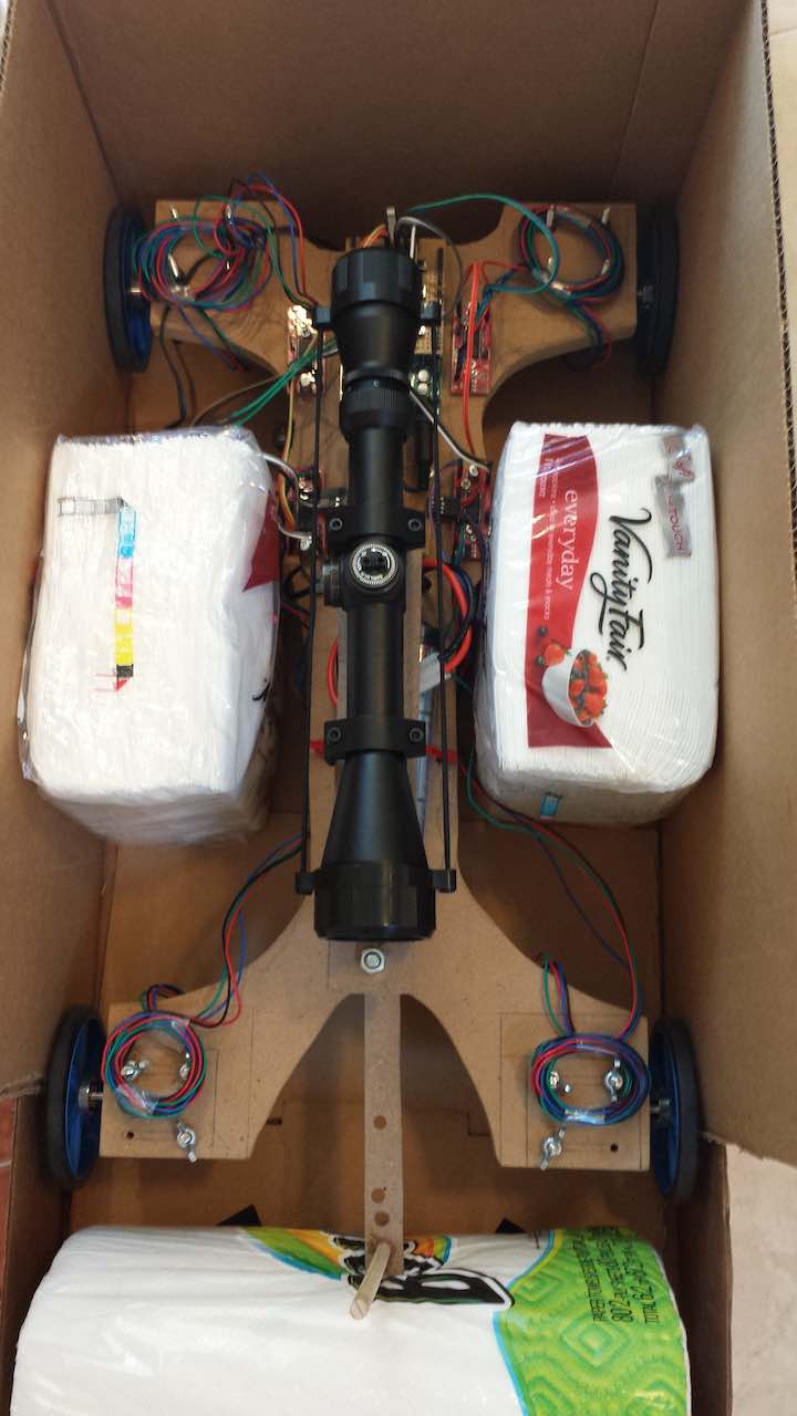
v3
During winter break, I started working on a new vehicle. There were multiple different areas on wanted to focus that was all aimed at making the fastest, most consistent, and easy to use vehicle possible.
Base
First off, I needed a platform on which I could more easily mount things. Since I eventually wanted to reassemble the RC car, I didn’t want to drill any holes in its base. I saw a lot of people online build their RC cars on top of carbon fiber plates, so I decided to do the same. Not having time to wait for a fine tooth bandsaw blade, I cut up the carbon fiber plate by hand using a Dremel. The resulting dust made quite the mess.


I highly recommend not doing what I did. Just use a bandsaw with a vacuum or like a water jet or maybe even a CNC mill. Definitely do not use a Dremel.
Steering
From a mechanical point of view, the entire steering assembly, from the screws to the axle to the wheel mounts needed a redesign. I started by cutting the carbon fiber to allow a wide range of adjustments to the steering. A couple of screws and large washers held everything down. I replaced the pulley bearings from v2 with actual high quality skateboard bearings. I made some mounts out of maple wood.
Next up was the axle. I stuck with using a 5/16″ threaded rod because that fit the 8mm bore of a standard skateboard bearing perfectly. The issue was attaching wheels to it. If I remember correctly, they use a 12mm hex. At the time there were no 5/16″ rod to 12mm hex converters, so I made my own by drilling out a 3mm rod to 12mm hex converter. Out of many tries, I only had maybe one or two that ended up being perfectly concentric. Eventually, I took my parts to Mr. Stedman, who helped out Troy from time to time, because he had a lathe. He helped ensure my wheels were perfectly concentric with the axle. This proved beneficial in improving the consistency of the vehicle.
Aiming
For the most part, the aiming system was completely carried over from v2. I’ll just go into a little more detail about its construction. I drilled a couple holes into a PVC pipe and put screws through it. These screws held in place a Class II laser pointer, which took quite awhile to find back in the day. Then I attached that assembly onto the top of the vehicle using liberal amounts of hot glue.
I also built a little target board that my partner would place at the target point to aid in aiming. Calibration involved first making sure the car drove pretty straight. I did this by checking to see if the deviation from the center line was roughly linear over multiple distances. Once the car drove straight, I adjusted the laser (using the screws) to the point where, over multiple distances, aiming at the middle of the target would make the car go straight along the center line.
Braking
One of the issues I had with v2 was that the brake was very one sided. Braking from relatively high speeds had a tendency to cause the car to jerk and turn. This is because the wing nut’s motion is forcibly stopped at one side of the axle and not the middle. Another issue was that I had to set the number of turns before braking by hand, which introduced a potential source of human error.
To fix these issues, I decided to go with an electronically triggered brake coupled with an encoder to measure rotations. The encoder was very straightforward. I wanted to use an optointerrupter I salvaged from a printer, so I made my own encoder wheel using some transparency sheets and acrylic. Completely unrelated fun fact – the transparency sheets came from my experiments in making custom MTG cards.
The electronic brake was a bit of a challenge. My idea was to attach a wing nut to the axle and use a servo which would move a piece of carbon fiber into the path of the wing nut when I needed to brake. Seeing that the servo reacted too slow to be a good brake, I came up with the idea of using a simple motor instead. When I needed to brake, the motor would more or less flick the brake piece into place. The wing nut’s rotation actually helped move this piece into place, stopping all motion.
Software wise, the entire braking took place in two steps. When the vehicle got close to its target distance, the Arduino cut power to the motor. The high speed of the vehicle gave it enough momentum to carry itself to the target line. Once the target line was hit, the electrically triggered mechanical brake would trigger and stop the vehicle completely.
Speed
The biggest part of the score for Electric Vehicle was easily the speed. We had to travel from rest to a certain distance as quickly as possible, so it would be more fitting to say acceleration was the most important part. I spent most of my time optimizing different factors to maximize it. Here’s most of those factors.
- Rear-wheel drive – I don’t think this made a huge difference, but changing to rear wheel drive also improved brake performance.
- Weight Distribution – Weight surprisingly didn’t make much of a difference but shifting the weight distribution to over the brakes and motors helped somewhat.
- Gear Ratio – A large gear ratio increases torque and thus acceleration significantly. There is an upper limit though because eventually top speed is decreased too much.
- Motor – A low KV motor helps here because it has higher torque. I also used a brushless one because of durability, controllability, and efficiency.
- Battery – I ended up using the lightest NiMH battery pack that still had enough current capacity for the motor.
- Wheel Diameter – The smallest wheel that would fit sacrifices top speed for much better acceleration.
- Tire Material – Rubber was my initial choice, but eventually I found out that foam tires worked even better.
- Tire Cleaning – Even on a perfectly clean gym floor, tires still pick up dirt over time which lowers friction. After every use I’d wash the wheels in some diluted Simple Green.
- Tire Treatment – To increase the tires’ friction even more, I applied some WD-40 before use to soften them up. Waiting a couple hours after application is necessary to let everything soak in.
- Technically applying WD-40 pushed the limits of the rules, which didn’t allow putting anything on the tires that would leave residue on the floor. After about 20 runs on a clean hardwood gym floor, I did notice a black streak. However, this didn’t really matter since at competition we only had 2 runs.
- Floor Cleaning – Since we weren’t allowed to use wet cleaners, I used a Swiffer with a Dry Pad to clean the floor before runs.
- Floor Type – I didn’t have any control over this, but the quality of the floor at competition was the single greatest factor that affected both speed and accuracy.
Electronics
With most of the rest of the vehicle done, I started on the electronics. For its ease of use, I did everything in Arduino. I made a shield with some buttons on it and connectors for the other parts of the vehicle. To display the distance, I soldered together a separate board which had seven-segment displays and shift registers. There really isn’t much else to say about the electronics. I just made sure to focus on ease of use.
Competition
v3 proved an excellent design. It performed really well up until the state competition at CalTech. They hosted the event on this really dirty floor so my accuracy was completely off. Much like the science building at Troy, no amount of sweeping could make that floor clean. Whereas I got 1st in Robot Arm and Forensics, I got 11th in Electric Vehicle. That poor performance served as a very strong motivator for me to invest a lot more time and effort into improving my vehicle for Nationals.
Luckily, at Nationals they used a pretty clean floor. The morning of competition, I applied just a bit too much WD-40 on the tires, so I was worried. Fortunately, at competition I took out the tires and it turned out that I had applied the perfect amount of WD-40. The tires had more grip than I had ever seen before. My run went about as well as I could’ve expected. The time was 1.3s. I was about 10cm off. At the awards ceremony, my heart was really racing. I was very surprised to have gotten 3rd place. I still remember Mr. Wahl high-fiving me as I walked back with my medal. My hard work had paid off.
Later on I realized that my 1.3s time, which was measured from 0.5m to 8m, approached the theoretical maximum, assuming a maximum coefficient of friction of 1, of about 1.0s. I was pretty proud of that. Somehow, I actually got a hold of the raw score sheet and found out that my vehicle was the fastest, except for one outlier that was way off, but I was beaten out in accuracy. I was also pretty proud of that since my main focus was speed.
Like v2, I also don’t have any pictures of v3. I do have some videos though.
Brake Testing. I fixed the jumpiness later on.
Regionals at UCI, home to the cleanest floors I’ve ever seen.
My Nationals run, although a bit cut off.
Comments