
Wireless Accelerometer
Written 8-19-19
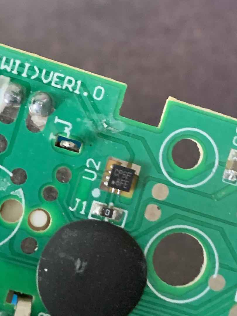
While taking apart and analyzing the circuit board of a Wii Nunchuk I got off eBay, I tried to figure out what chips they used. The main microcontroller was a glop-top so no luck there. There was also an I2C EEPROM chip which I did end up desoldering and figuring out how to use. However there was one chip that I just couldn’t figure out the part number of. The markings on it didn’t bring up any useful information, but I assumed it was an accelerometer because the Nunchuk has one.
Figuring Out The Mystery Chip
Based on the pinout of the EEPROM and following the traces, I deduced that the mystery chip communicated over I2C and was on the same bus as the EEPROM. After connecting an Arduino to the thankfully exposed I2C test points, I ran some I2C scanner code to figure out the addresses of the devices on the bus. There were two devices, 0x50 matched the EEPROM, so the other, 0x4C, was the accelerometer.
In hindsight, literally Googling “0x4C accelerometer” would have resulted in finding the datasheet that likely matched the chip. I somehow didn’t think of that at the time because the Nunchuk was so cheap. Well, I did end up learning a lot in the process, so it was a blessing in disguise.
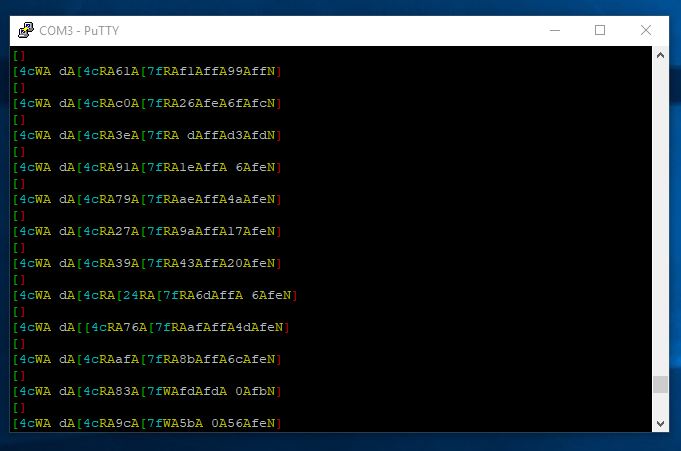
I started looking into I2C sniffers to analyze all the traffic on the I2C bus. I had a bunch of STM32 Blue Pill boards lying around, so I looked to see if someone had written code for it. To my pleasant surprise, someone had. I loaded the project into STM32CubeIDE and tried it out. First, I tried analyzing the communication between an Arduino and Wii Nunchuk and it worked perfectly. I could see all the addresses, data, start conditions, Acks, etc.
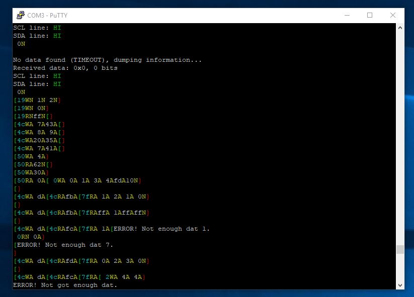
However, when I tried analyzing the I2C bus that housed the accelerometer, I got a bunch of gibberish. As it turns out, the I2C communication for a Nunchuk runs at 100KHz, but the accelerometer and EEPROM bus runs at 400KHz. Since I didn’t have the money for an expensive logic analyzer, I looked around the internet for an I2C analyzer that could analyze a 400KHz bus but to no avail. Using the I2C scanner code from earlier as a test signal, the fastest bus I could read was about 150KHz.
Making a 400KHz I2C Analyzer
Knowing a bit or two about optimizing and speeding up code, I took a look at the code for the STM32 sniffer. I first tried overclocking the chip from 72MHz to 128MHz by setting the PLL multiplier to 16. To my surprise, this worked flawlessly and I was able to scan buses up to 250KHz. I wondered if I could overclock it even further. I made a new project in STM32CubeIDE to test this out. The maximum PLL setting was 16, which limited me to 128MHz with an 8MHz crystal oscillator, so I replaced the oscillator with a 16MHz one. I immediately ran into stability issues. Dialing the settings back, I was able to overclock the STM32F103C8T6 to 144MHz, a 100% increase!
Still, I was only able to read buses of up to maybe 300KHz. The next step was optimizing the code. I heard that the HAL library used to control the GPIO adds a lot of overhead, so I looked into that first. It turns out every HAL GPIO access call does a bunch of checks which weren’t necessary in my use case. After a bit of tinkering, I was able to replace all the HAL calls in the code with register calls. I basically just replaced one function, as shown below:
void HAL_GPIO_EXTI_Callback(uint16_t GPIO_Pin) {
    uint8_t datum;

    if (GPIO_Pin == GPIO_PIN_8) {
        // Clock triggered; bit received
        if (GPIOB->IDR & GPIO_PIN_9) {
            datum = 1;
        } else {
            datum = 0;
        }
    } else if (GPIOB->IDR & GPIO_PIN_8) { // SDA pin necessarily
        // START or STOP condition
        // A for START, B for STOP
        if (GPIOB->IDR & GPIO_PIN_9) {
            datum = 'B';
        } else {
            datum = 'A';
        }
    } else {
        // Nothing interesting here...
        return;
    }

    buffer[bufferPos] = datum; // Store the received bit in the buffer
    bufferPos++;
    if (bufferPos >= I2C_BUFFER_SIZE) {
        bufferPos = 0;
    }
    //if (bufferPos == bufferStart) printf("ERROR! I2C buffer too small!\r\n"); // Buffer overflow! //never really happens
}
After that, I was able to read up to around 350KHz I2C buses reliably. The next thing I was going to try was clock stretching, but I found that the decent reliability at 400KHz was good enough for my goal of reverse engineering what commands to send.
Revealing Its Identity
With the commands captured I was finally able to hook up the mystery chip to my Arduino and directly access the raw data off of it. I correctly assumed that it gave out readings in order X, Y, Z, but the data was jumbled at first. Turns out this chip sends out the LSB byte first then MSB byte. A simple bit shift later and everything was working.
I began to wonder what the chip actually was so I Googled “0x4C accelerometer” and I found some people talking about a MC3451 so I checked that out. Looking through the datasheet, everything seemed to match up perfectly with regards to register locations. The manufacturer, mCube, doesn’t have that many different offerings so I looked at the datasheet of each and found that the model that best matched my mystery chip was the MC3413. The initialization commands all matched up to reasonable settings on the chip. Still, trying to read the PCODE register returned an incorrect value, so it’s likely my mystery chip isn’t exactly an MC3413 but perhaps a knockoff or reject or something.
Figuring Out the ATtiny817
Initially I was going to use a standard Atmega328P-AU for the microcontroller but I found that it was too big and overkill for my use case. My eyes turned to the ATtiny817 that I had sitting around for over a year. On paper it had every feature I needed so I took out my ATtiny817 Xplained Mini board and fired up Atmel Studio 7. At first I looked through the datasheet and learned how to write directly to the registers controlling I2C and SPI, but I found out that using Atmel START was far easier. The code doesn’t use any unnecessary checks or abstractions, so speed-wise there wouldn’t be much difference.
Hooking Up The USART
Well technically I’m using UART because it’s asynchronous. Atmel START provides USART_0_write() and USART_0_read() for UART communications, but I wanted to get that printf() functionality. Doing some research online, I found that I just needed to add a few lines of code to usart_basic.c. I also wanted to get scanf() working, so using some good old educational guessing I got that working too.
//Add these lines below #if defined(__GNUC__)
int USART_0_printCHAR(char character, FILE *stream) {
    USART_0_write(character);
    return 0;
}

int USART_0_receiveCHAR(FILE *stream) {
    return USART_0_read();
}

FILE USART_0_stream = FDEV_SETUP_STREAM(USART_0_printCHAR, USART_0_receiveCHAR, _FDEV_SETUP_RW);

//Add these lines below #if defined(__GNUC__) in USART_0_init()
stdout = &USART_0_stream;
stdin = &USART_0_stream;
Integrating I2C
The next step was hooking up the MC3413 to the ATtiny817. I wanted to make sure I could use the MC3413 with a board of my own design, so I desoldered it using my reflow oven and soldered a bunch of tiny wires to the pins.
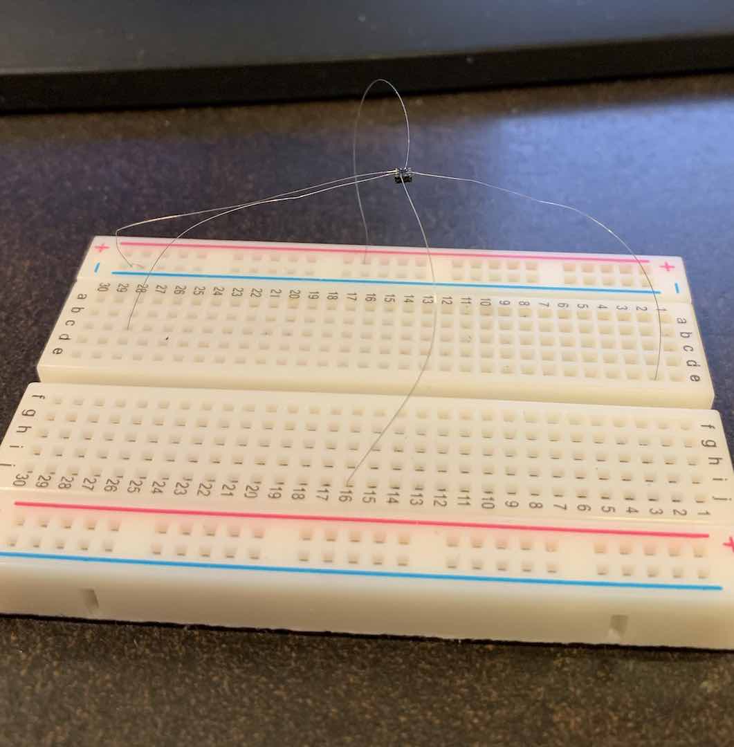
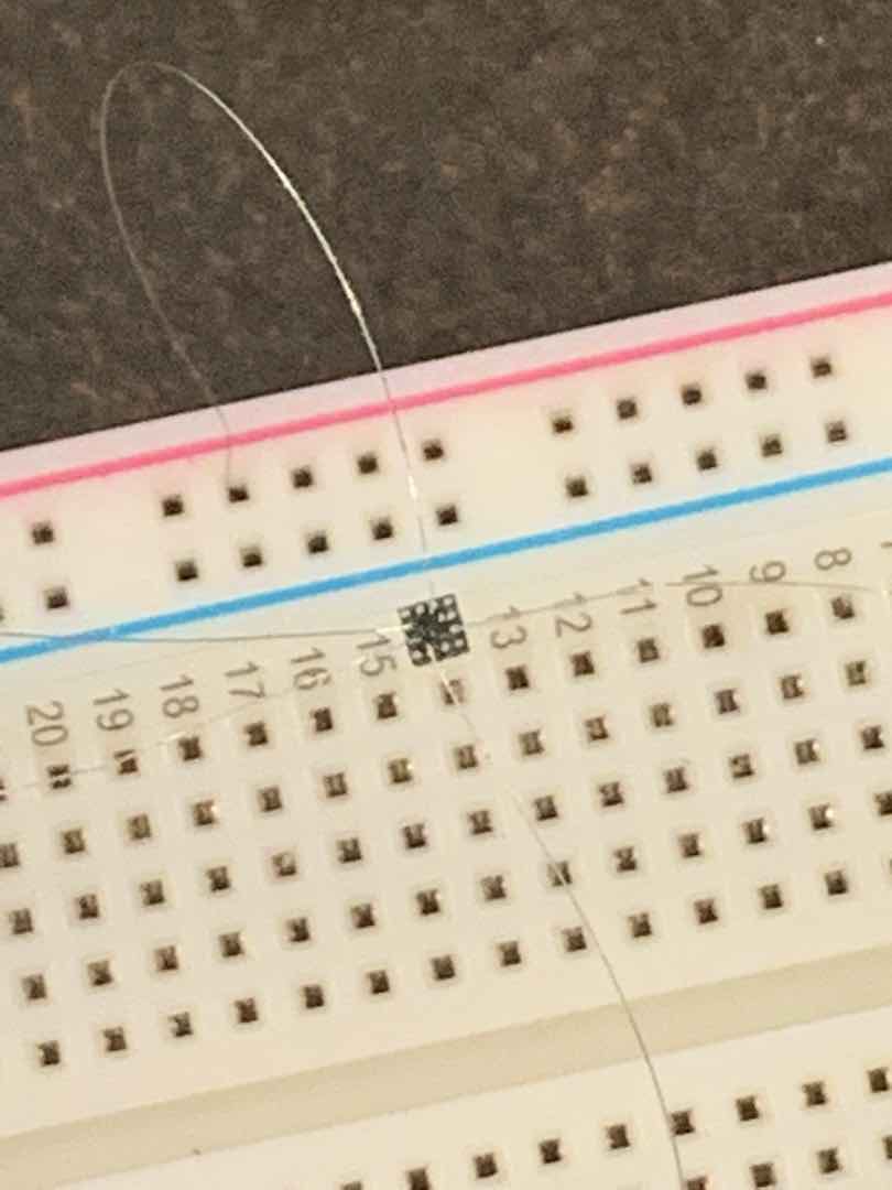
Despite how fragile the wiring looks, it actually works for testing.
Atmel START also provides the i2c_master.h and i2c_simple_master.h libraries for using the I2C interface. It defaults to interrupt mode when you add the module, so make sure you enable interrupts in the SREG register. I was coming from the Wire library for Arduino, so the i2c_simple_master.h library provided a smooth transition.
I2C generally uses the concept of addresses and registers when communicating. Writing to a register involves sending the device address (with a write bit), the desired register, and finally any data to write. Here’s the code I used to initialize the MC3413:
I2C_0_write1ByteRegister(accel_addr, 0x08, 0x0A);
I2C_0_write1ByteRegister(accel_addr, 0x20, 0x35);
I2C_0_write1ByteRegister(accel_addr, 0x07, 0x01);
Reading from registers is similar. First you’d send the device address (with a write bit) and then the desired register. Then you’d send the device address again (with a read bit this time) and then read in as much data as you need. Here’s the code I used to read the accelerometer data from the MC3413:
I2C_0_readDataBlock(accel_addr, 0x0D, dat, 6);Synthesizing SPI and nRF24
Like with I2C, Atmel START provides a really nice spi_basic.h library. I chose to use polling mode instead of interrupt mode because I was still a beginner and didn’t need the added functionality of interrupt mode. It also provided an easy transition from the Arduino SPI library. Here’s the 4 methods to be aware of:
uint8_t SPI_0_exchange_byte(uint8_t data);
void SPI_0_exchange_block(void *block, uint8_t size);
void SPI_0_write_block(void *block, uint8_t size);
void SPI_0_read_block(void *block, uint8_t size);
They’re pretty self explanatory. SPI is generally much simpler than I2C in how to use it. There’s a chip select (CS) pin for each slave. To communicate, just pull the CS pin low and then start sending/receiving data.
Finding a good nRF24 library for Atmel Studio 7 yielded no results, so I decided to figure out how to port TMRh20’s RF24 library. Looking through the source code, it appears very well written. It uses the Arduino SPI library instead of low level register manipulation so swapping out any SPI calls with spi_basic.h equivalents would do the job. I ended up only porting over the functionality that I needed, mainly interrupt support and radio settings. My code can be found here.
Initializing External Interrupts
One really nice thing about the ATtiny817 is it has interrupt capability on all pins, and supports all interrupt types instead of just pin change like on the Atmega328P. After using Atmel START to setup the pin, I implemented the ISR routine. Every pin belongs to a certain register, so the corresponding interrupt vector gets triggered when the pin’s interrupt triggers.
ISR(PORTB_PORT_vect) {
    PORTB.INTFLAGS |= 1 << 0; //clear interrupt flag
    uint8_t tx, fail, rx;
    RF24_whatHappened(&tx, &fail, &rx);
    if (tx) { //on success
        PORTA.OUTSET = 1 << 6; //turn off red
        PORTA.OUTCLR = 1 << 7; //turn on green
    } else {
        PORTA.OUTCLR = 1 << 6; //turn on red
        PORTA.OUTSET = 1 << 7; //turn off green
    }
}
Putting It All Together
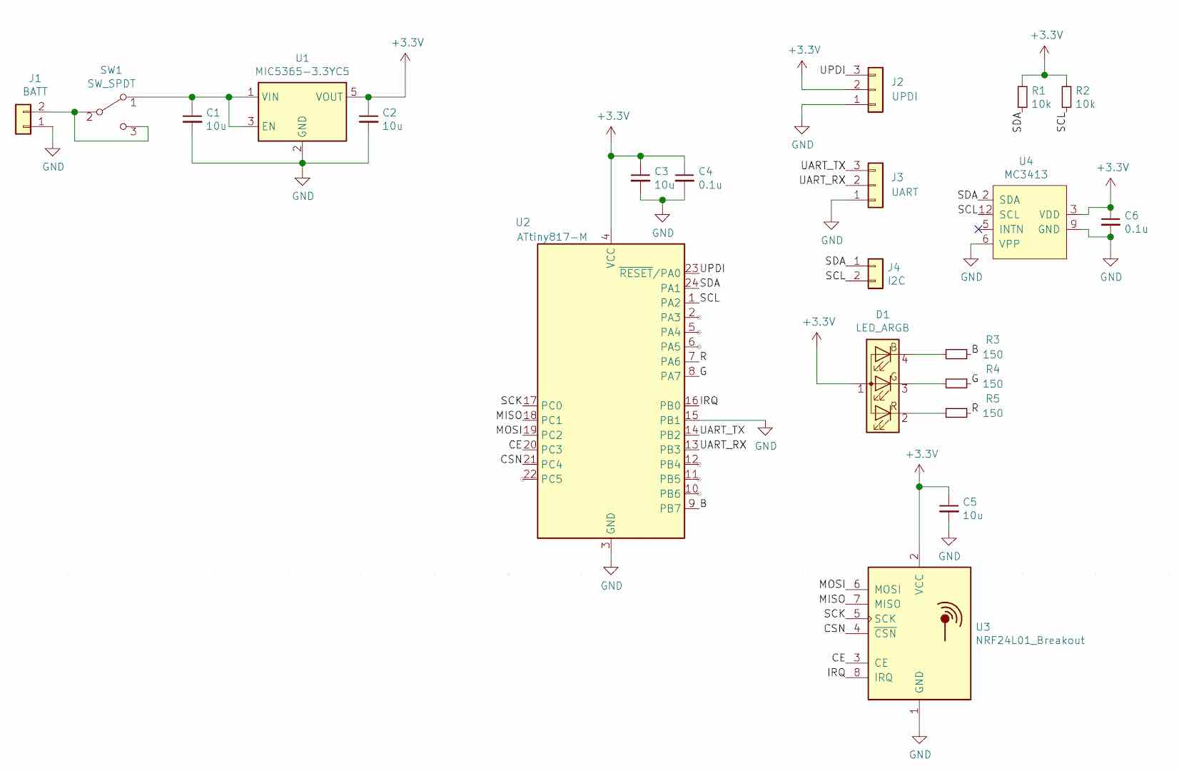
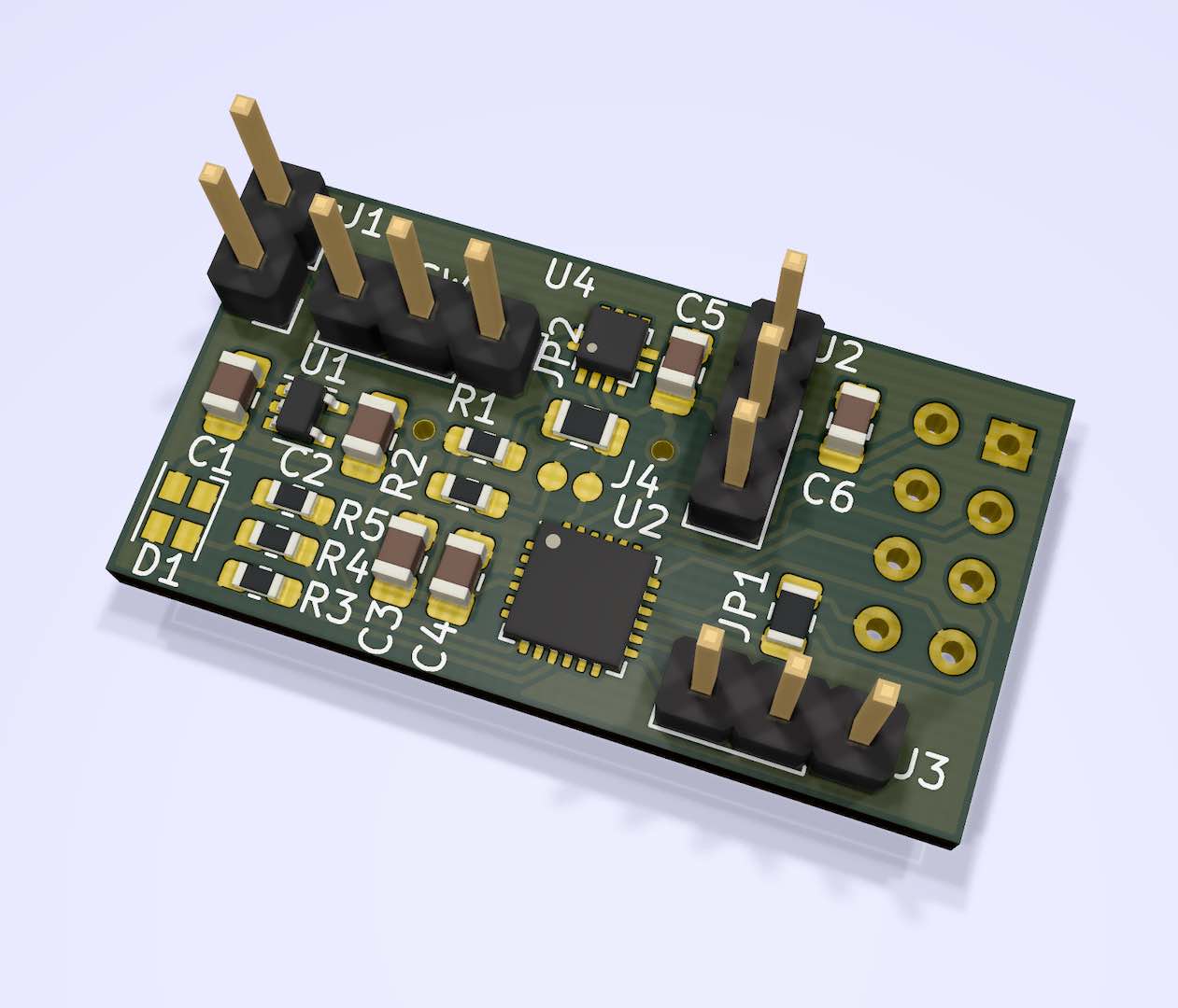
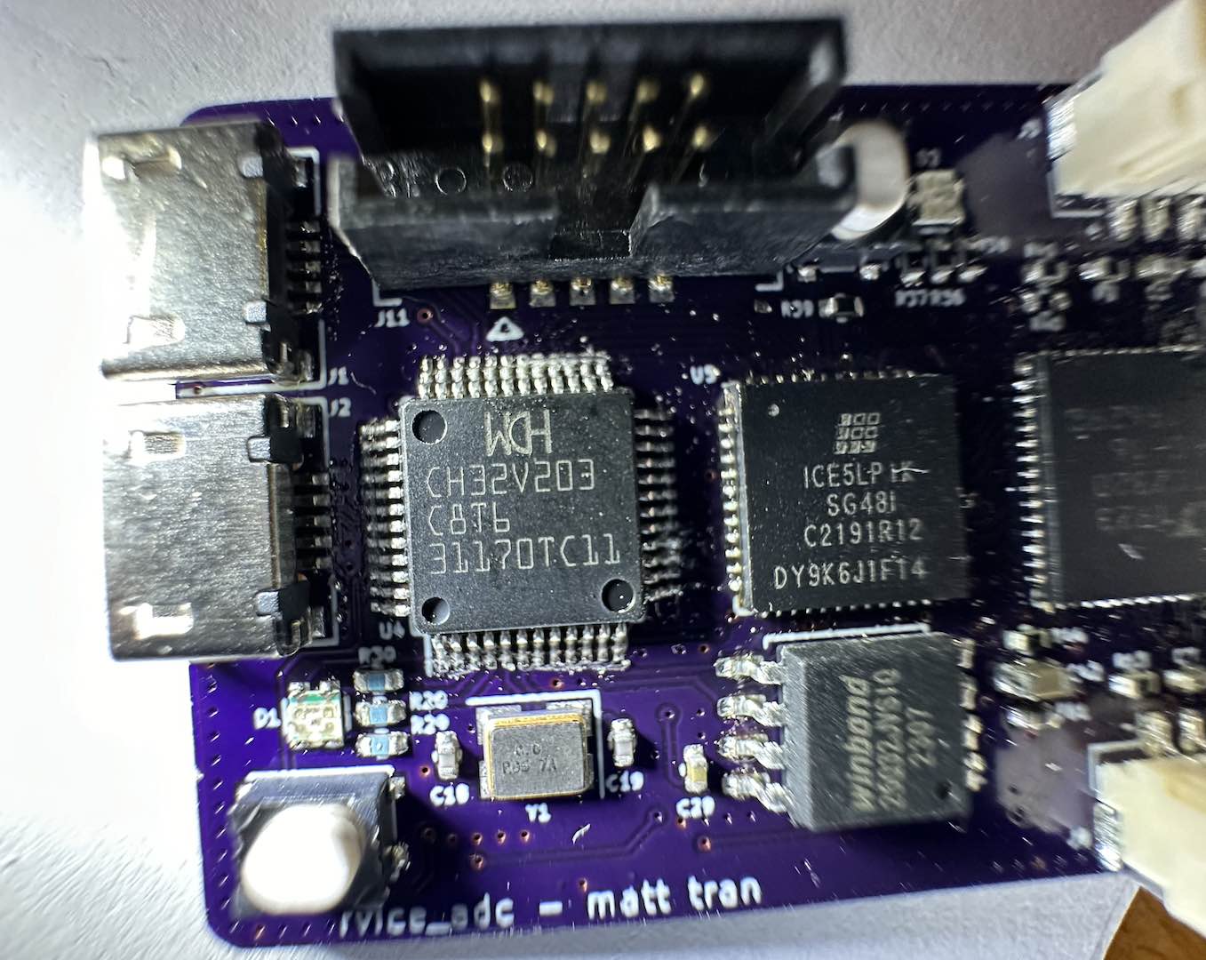
With pretty much every component tested and working, it was time to make the PCB. I threw all the components into KiCad, where I did have to make my own schematic symbol for the MC3413. The VLGA-12 footprint it used was available though.
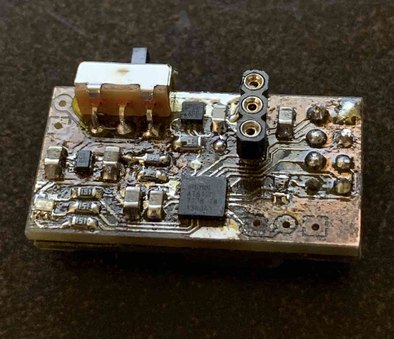
As usual the PCB manufacture was pretty easy, but soldering the MC3413 proved quite the pain with my lack of solder paste and the VLGA-12 package. After several reflows and lifted traces, I did get it pinned down. I did accidentally pull up the TX trace so couldn’t use UART. That did allow me to experiment with the UPDI debugging interface, so it worked out.
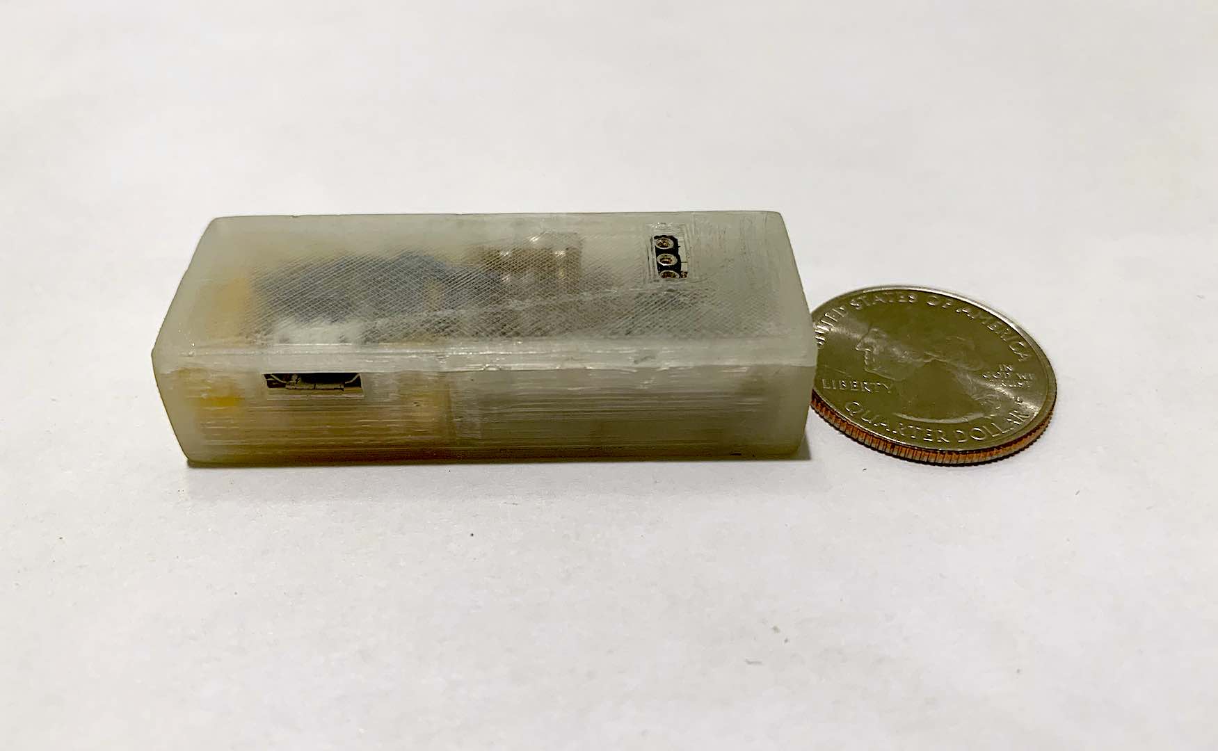
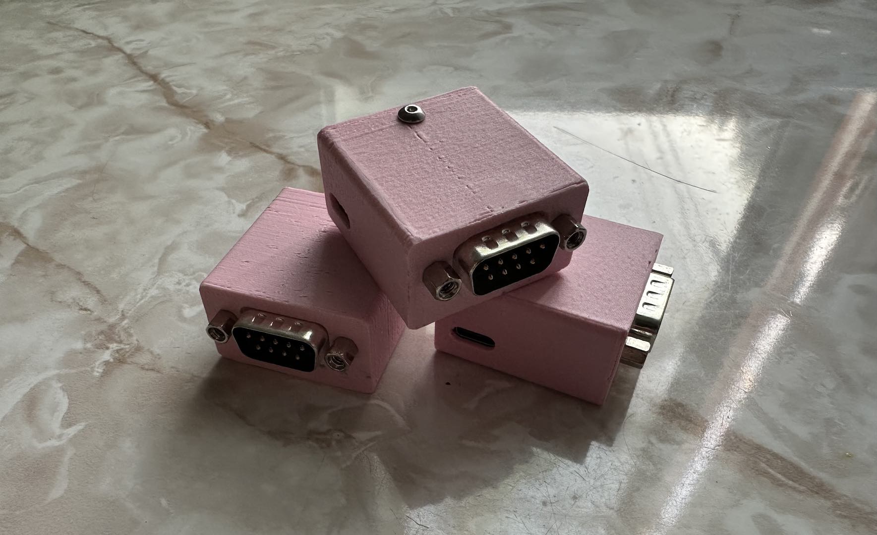
After putting the board together, I attached a LiPo I salvaged from my old Pebble Steel along with a TP4056 charger board and threw it all into a little 3D printed case. After some meticulous sanding to get all sides smooth and level, I was done.
Demonstration
One of the things I could never quite figure out, in part due to my relative inexperience at the time and also because I was always encumbered by wires when testing, was how to distinguish between swings and clashes. I literally couldn’t find any code at the time to help me out except for one person who used the Z accelerometer measurement with some thresholds which was still mostly wrong.
With some basic knowledge of physics and accelerometers, it became pretty clear that a swing provided a low acceleration and a clash a high acceleration. Thus I just needed to combine the X, Y, and Z measurements into a measurement of the gravity vector and just look at that.
As the theory would predict, there’s a pretty clear difference between swings and clashes. I basically facepalmed myself multiple times after this realization because of how much work I put into trying to figure out this simple fact a couple years ago.
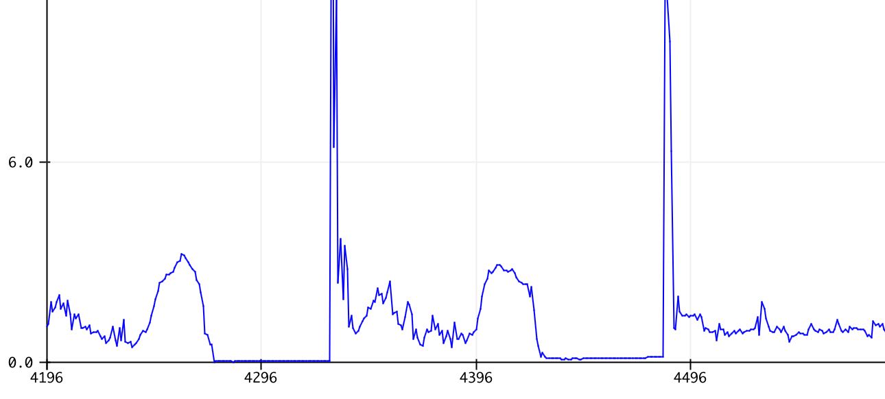
Of course, no accelerometer demonstration would be complete without showing the weightlessness experienced in free fall.
Comments