
BSWelder v1
When it comes to working with lithium batteries such as the 18650s I used in my lightsabers, it’s never really a good idea to solder wires directly to them. Prolonged exposure to high heat is a no go for their chemistry. The proper way is to spot weld nickel strips to them and then solder wires where necessary. Nickel is really easy to get solder to stick to compared to 18650 battery terminals. However a decent battery spot welder can easily be upwards of $150, which is a bit much for something I’d seldom use. Considering the plethora of people online making their own battery spot welders, I decided to take the DIY route.
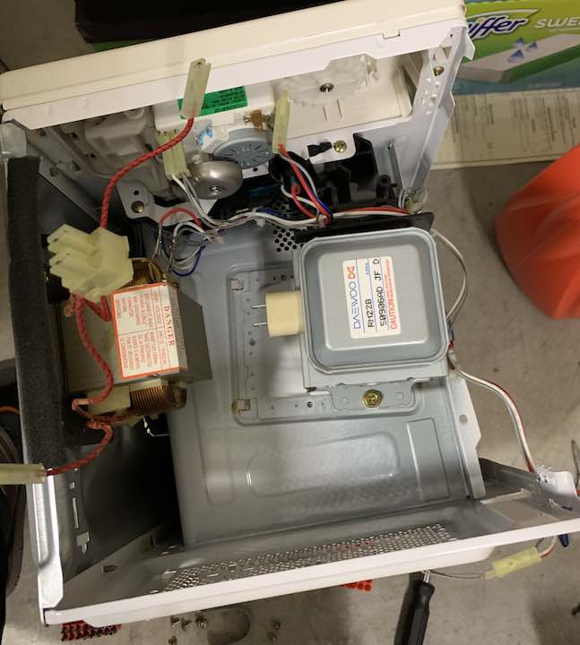
Generally speaking, a battery spot welder works by using a very high current – 100s of amps – to quickly heat and weld two pieces of metal together. The brevity and localization of the heat is what makes it perfectly safe for batteries. Producing and controlling this current pulse is the difficult part. A common way is to use high power batteries and a giant relay. Typically a car battery is used but those cost about a $100 which meant I wasn’t taking that route. Another popular way is to modify a microwave transformer. After finally finding a broken microwave off the street, I was in business.
Salvaging a Microwave Transformer
Note that taking apart a microwave is incredibly dangerous due to the high voltages it uses. Even unplugged, the high voltage capacitor inside can still pack a lethal punch so be careful if you do this. Make sure to discharge it before handling it. Also careful with the magnetron because the beryllium oxide in it is carcinogenic if airborne.
Modifying the Transformer
After removing the transformer, I needed to remove the secondary coil so I could rewind my own. There’s two main approaches to this. The first and probably what I should’ve done is to take an angle grinder to the secondary to get the ends off and a screwdriver and mallet to get the rest out. The second is to take an angle grinder to the weld that connects the top block and remove the secondary that way. What I found strange is that the weld actually shorts all the laminations together, but turns out there’s a reason for that.
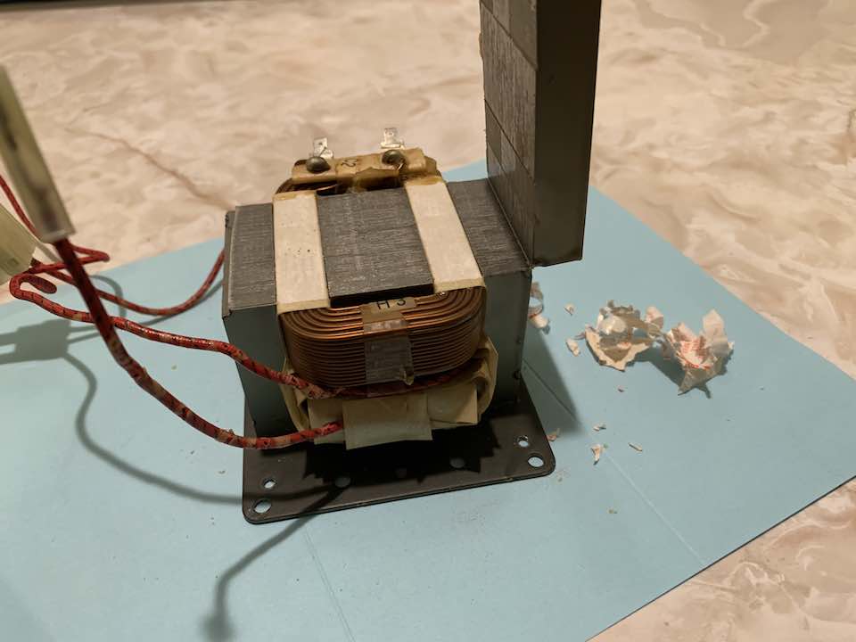
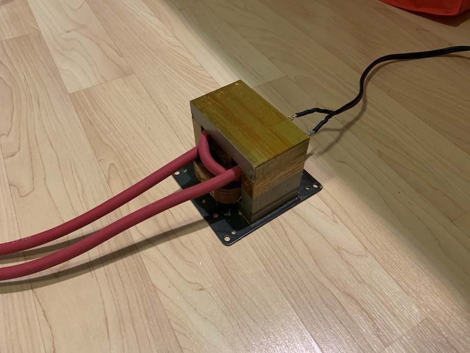
Make sure to also remove the magnetic shunts and small middle coil. Just keep the primary. To make the new secondary, I used some 4 gauge welding cable, barely squeezing in just over a turn. Then I used a lot of Kapton tape to somewhat reconnect the top half. I get about 1.5V AC out.
Controls
Next up is actually generating the pulses of current, which meant finding a way to quickly turn on and off a highly inductive load. If I learned anything from making my PCB laminator, it’s that TRIACs without a good snubber can have trouble turning off inductive loads. To make my life easier and to try something new, I bought an SCR. They can also have issues with inductive loads since internally they basically have a TRIAC with some control circuitry. I was prepared to spec out a snubber circuit, but to my surprise the SCR worked without one. To do viability testing I used some timing numbers from here and 3D printed an electrode holder to jerry-rig a little setup.
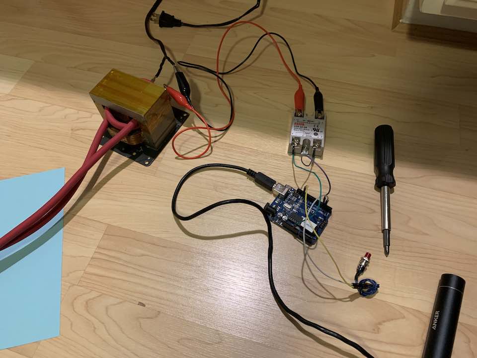
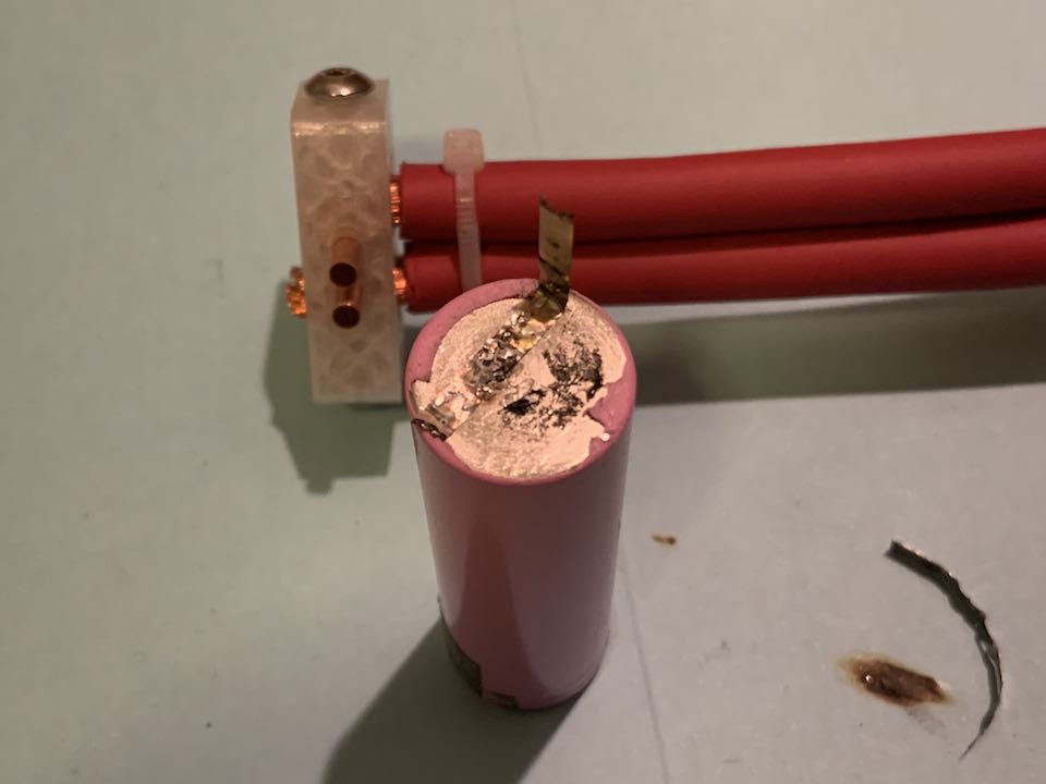
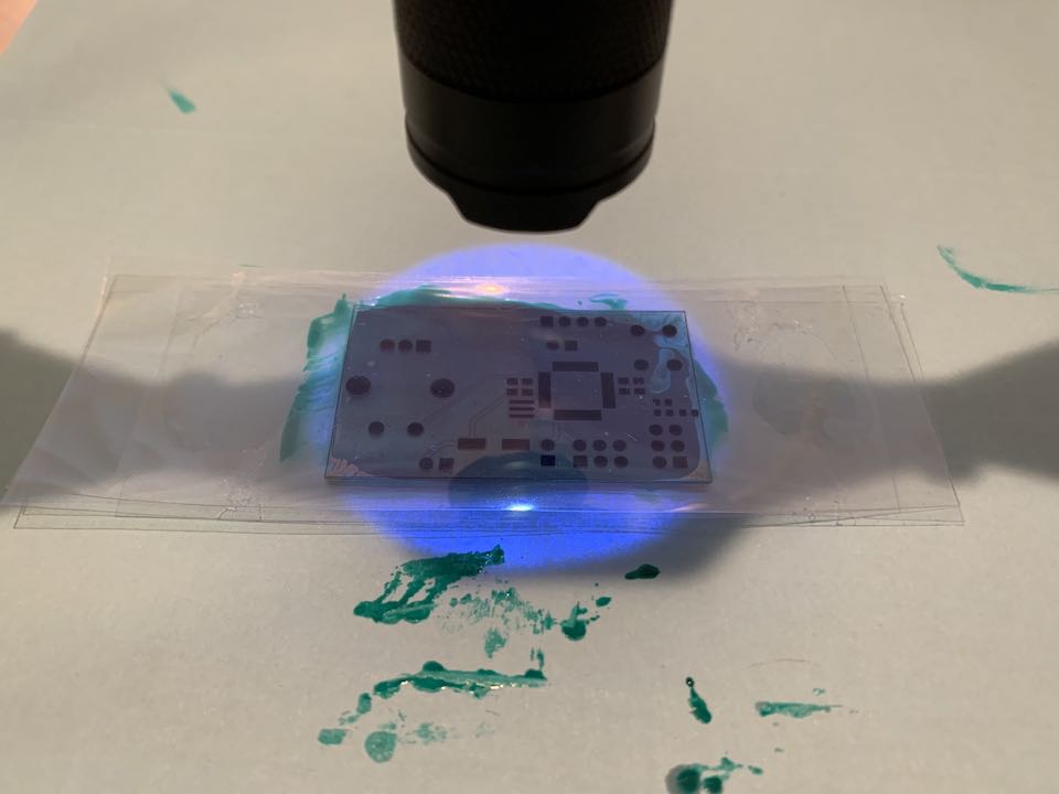
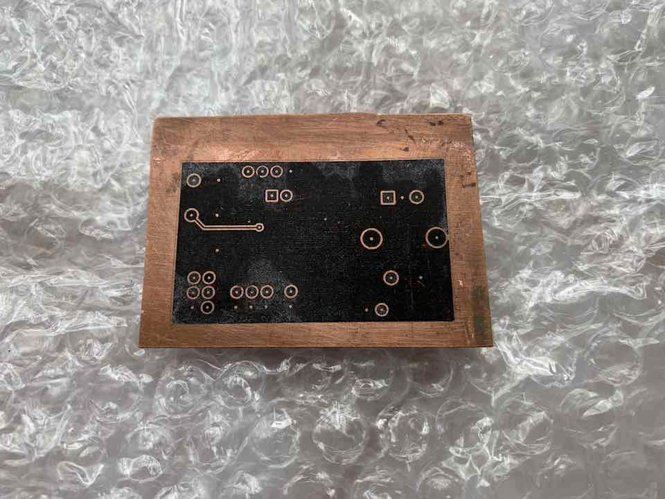
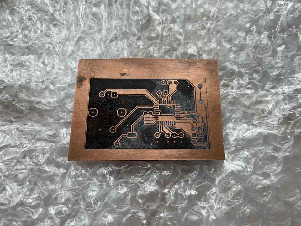
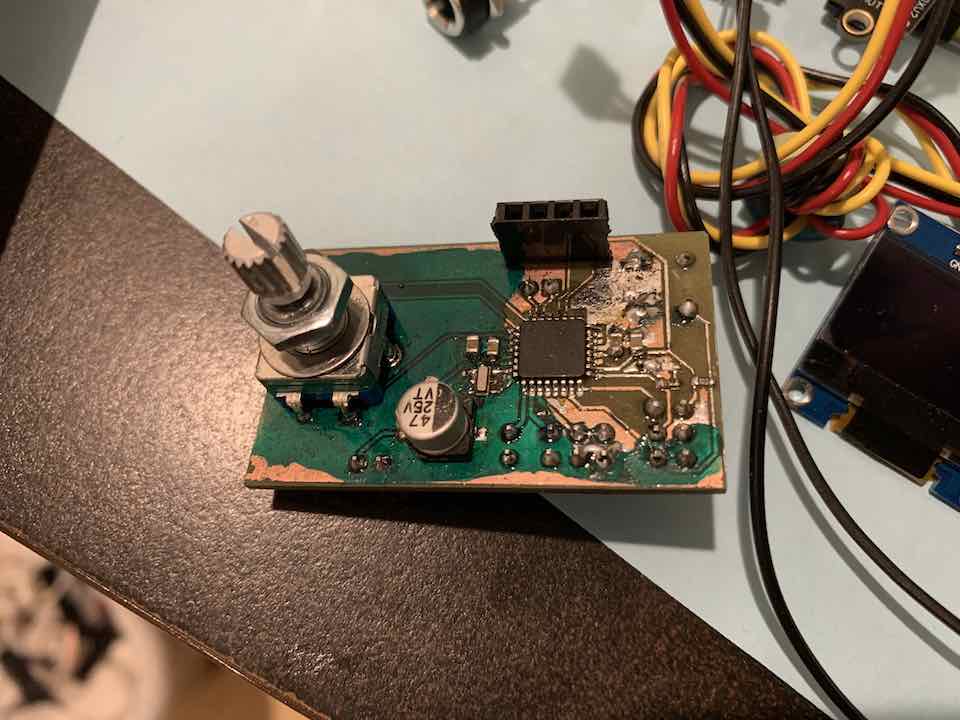
To my surprise, it worked really well. Not pretty since both the battery and the nickel strip were salvaged, but usable. The welds were stronger than the metal itself, which is a good sign. With that I proceeded to making rest of the electronics. I’m the type of person that likes UI, so I used this as an opportunity to use an EC-11 encoder I got off eBay and experiment a bit with the code. It was also my first attempt at a double-sided PCB.
Code
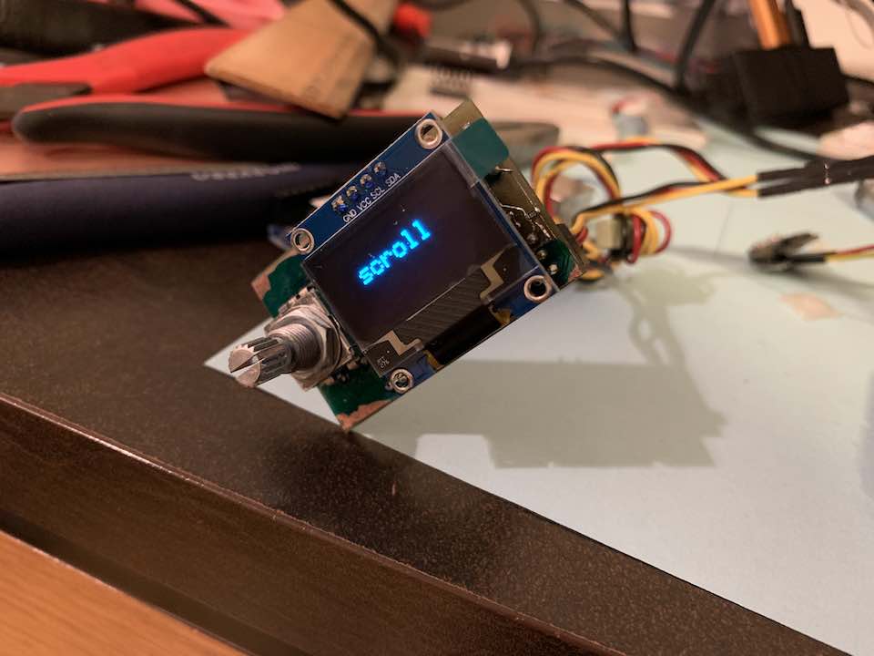
The code was pretty interesting to write. Nothing too complicated as I banged it out in about an hour including all the testing. I really liked the UI I developed for it, which was inspired by what’s commonly used in 3D printers. Scrolling through different options is quite satisfying. One thing to note is that EC-11 encoders go through a full cycle with each detent, which corresponds to 4 ticks per detent using the common X4 encoding. It was also the first time I used EEPROM on Arduino. To reduce wear on it, I only save settings when a user selects the save option. Also note that uploading code to a standard Arduino erases its EEPROM, so I changed the fuse to stop that. Anyway, here’s the code.
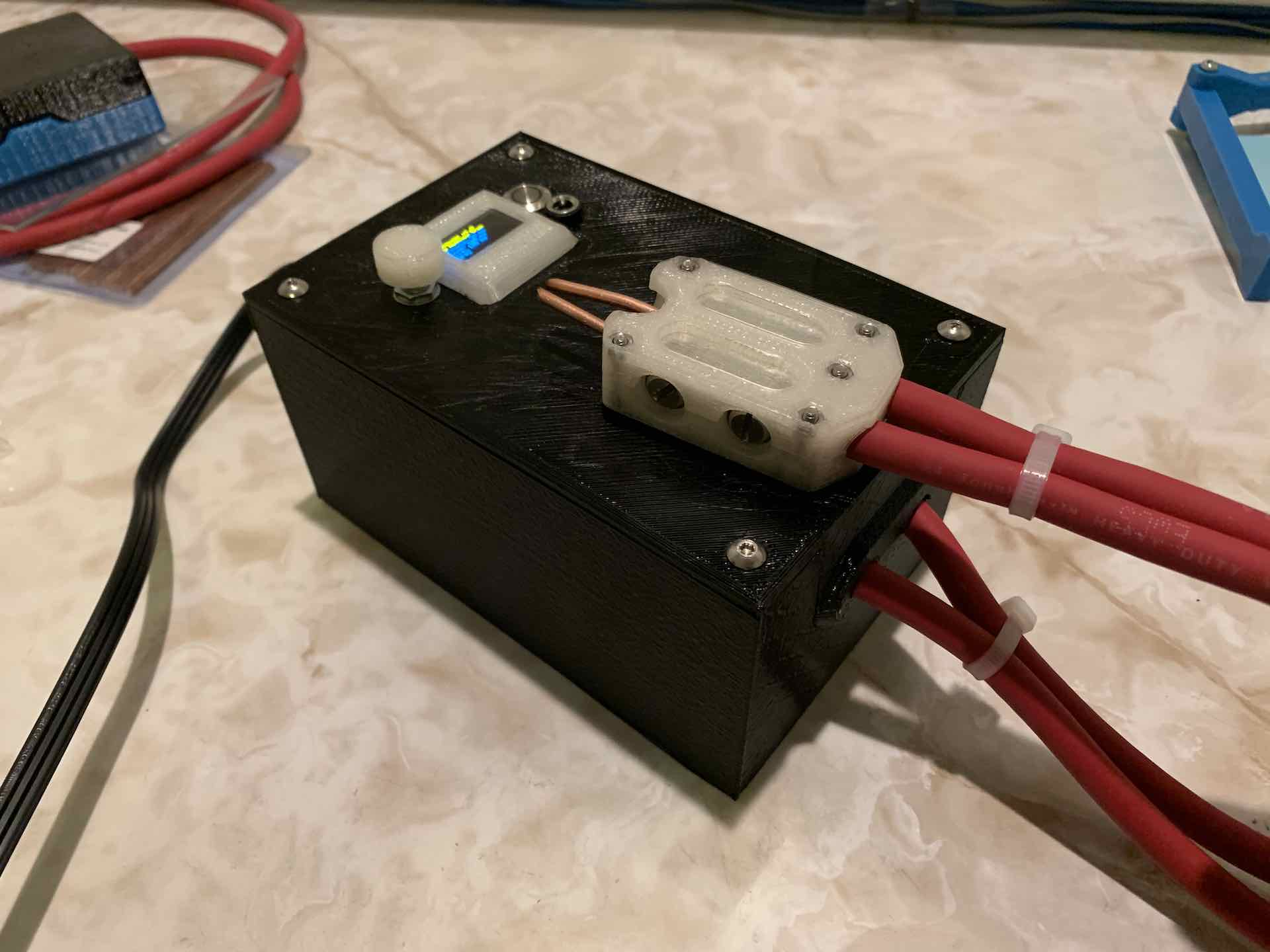
Case
With the electronics done, I put together a really simple case. Forgetting to bring home my caliper was certainly a problem but I got through it with solid estimations using a ruler. I also designed a proper electrode holder since PLA melts under the heat of the welder. Since I didn’t have any good machining tools nor the stock, I bought some metal parts from Home Depot that work pretty well as holders.
Testing
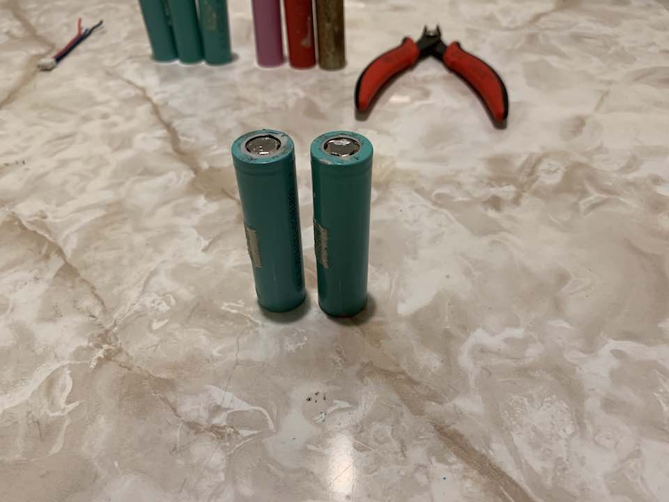
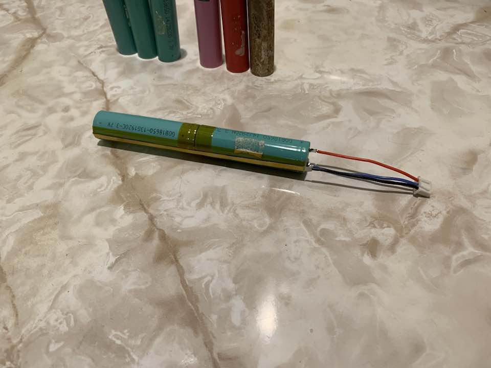
With everything finalized, I tried to make a little battery pack. Taking apart a friend’s broken battery bank to get some cells, I noted that all the terminals were scratched by a grinder of some sort. This is really clever since a clean metal surface is much easier to weld to, so I made sure to do this when I made my pack. To make a weld, simply place the nickel strip on the battery along with the electrodes. Apply a good amount of pressure and then press the trigger. I even made a foot switch, which I somehow didn’t get a picture of before heading back to school, to help out with this.
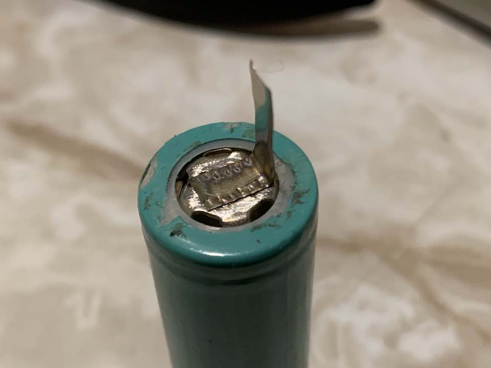
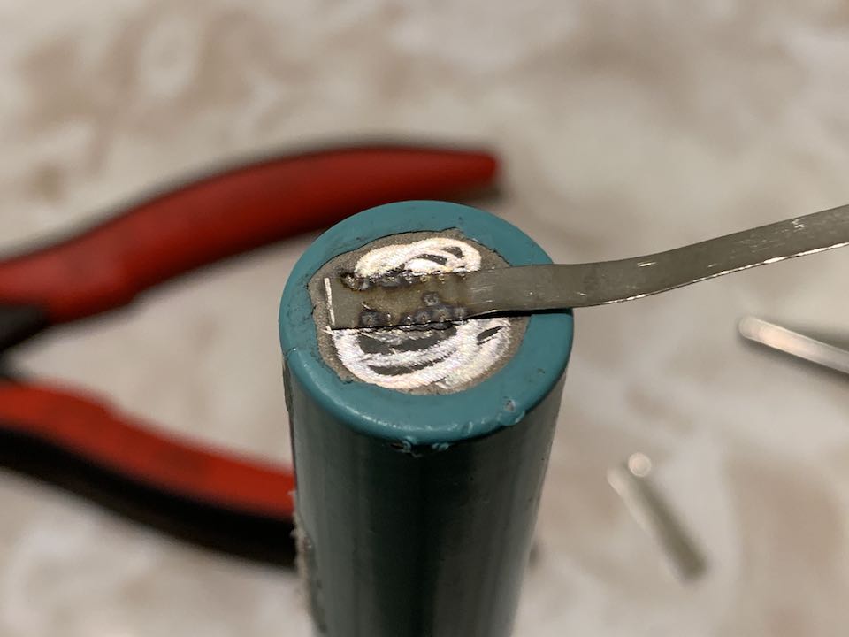
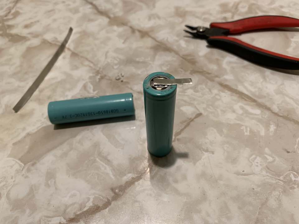
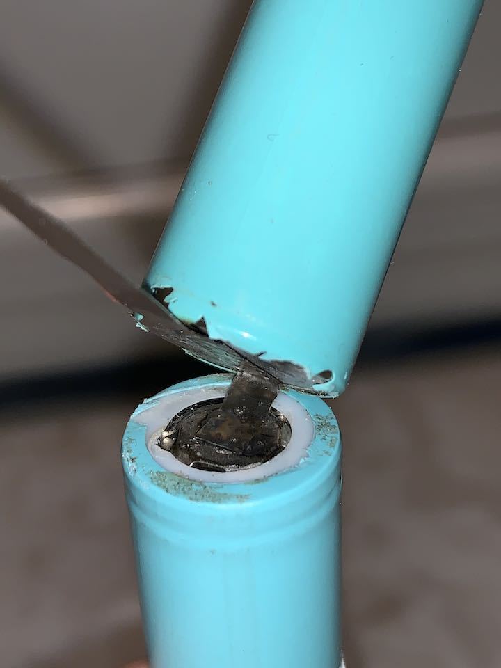
To ensure thorough testing, I went a bit overkill with the number of welds for each strip. I’ve noticed that one of two things happen with each weld. Most of the time the nickel strip gets red hot but sometimes there’s only sparks which in my experience result in cleaner and just as strong welds. It’ll take some more practice and tweaking to get this thing working perfectly.
Overall the welder cost about $40 to make, which was an absolute win. And the pack turned out perfect!
Comments