
Concept Micromouse v1
After taking the Micromouse DeCal and helping teach it for a semester, I decided it was time to try my hand at designing a Micromouse myself. There were a few things about our current Micromouse that I thought could be improved and some design decisions that I didn’t really understand the rationale behind. I grabbed a bunch of parts that we use in our current Micromouse and gave myself a week of winter break to put something together.
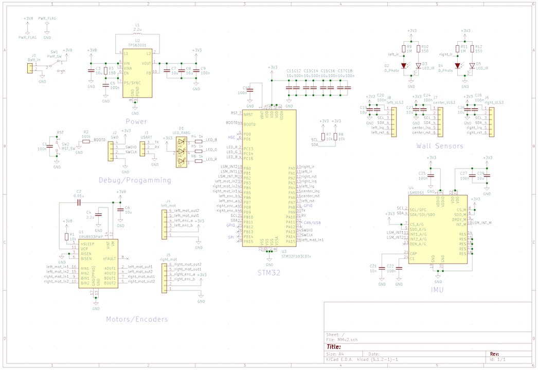
Since I’d want this design or something like it to eventually replace our current Micromouse, I set the overarching focus for this design to be cost-effective, easy to manufacture, and easy to develop code for. From a systems perspective, we can divide the Micromouse into several key sections: Power, Compute, Sensors, Effectors. I’ll go over several of the changes I made along with the rationale behind them.
Power
Battery
In our original Micromouse, we used a rechargeable 9v battery, which in my opinion had little to offer. I decided to switch to a 1S 3.7v LiPo battery which offers a slightly larger capacity, much higher discharge capability, fast charge rates, and a flat form factor all for about the same weight. The new form factor allowed me to flatten the design by a lot, improving maneuverability. Despite the lower voltage, my Micromouse still achieved speeds of ~500mm/s which is on par with what the 9v could do. I’d imagine using a 2S 7.4v LiPo pack would boast even higher speeds.
Regulator
Since I was trying to move to ARM-based microcontrollers, I had to switch to a 3.3v regulator. For my design, I used a TPS63001 that I had lying around. This section doesn’t really matter too much as long as it can supply at >100mA. An LDO would work just as well while being easier to solder and using fewer components.
Compute
Perhaps the biggest change I made to this Micromouse was the decision to switch from the Arduino Nano (ATmega328P) to a STM32F103CBT6, which is commonly found in those popular STM32 Blue Pill boards. Along with the far higher clock speed, the STM32F103CBT6 boasts 128KB of flash, 20KB of SRAM, and 32-bit computing. Even more, the STM32F103CBT6 offers external interrupts on all pins and a 12-bit ADC, opening up more interesting possibilities for sensors. Flexibility in development is the real key here.
Cost-wise, this chip is about $1 each on AliExpress, making it competitive with the Arduino Nano. The only issue is having to get a programmer, but it’s possible to use USB DFU to do that job. Soldering an LQFP chip can be a bit difficult, so I’m considering just using a full size STM32 Blue Pill board which costs about $2 each. Still, with some pointers and lots of solder wick, I think soldering an LQFP chip is achievable for even someone who hasn’t soldered before.
From a development perspective, it’s very easy to develop and program the STM32F103CBT6 using Arduino. However, I think that using Mbed can be even easier, as well as opening up the possibility of using an RTOS. In fact, I developed all the code I used for my concept using Mbed, applying object oriented principles and threads to clean up and organize everything. This makes it easier to keep the main focus on just the algorithm.
Sensors
IR
Doing research into other Micromouses, I found that most of them tend to use some sort of IR sensor to detect walls. After some testing, I noted that they don’t work well on angled surfaces, especially reflective ones. Head on, they do a great job for anything <10cm away. Overall, they’re not particularly consistent and are only really good enough to detect if a wall is there or not. I decided to place two IR sensors onto my Micromouse, one on the left and one on the right. This doesn’t affect maze solving much, but should help with realigning the Micromouse’s sense of which square it’s in.
VL53L0X
When I was writing MMSim, I finally understood why our Micromouse had distance sensors that were angled. We can use them to detect walls further than the square we are currently in. I wanted to keep this functionality so I kept 3 VL53L0X sensors on my Micromouse like the original design. For mainly aesthetic reasons, I didn’t want to angle the sensors inward so instead I did some CAD drawings to find the optimal angle of 22° to place the left and right sensors. For fun, I decided to also plot the placement of our original sensor and to my surprise, it’s field of vision perfectly matched the center of the walls to the front right and left. That’s what I was going for when I chose the angle for my sensors.
Doing some testing, I noted that these sensors were real nice. They are good for distances >1cm and still work on angled, even reflective, surfaces. They’re also pretty cheap and have many libraries already written for them. A great choice to keep in the Micromouse.
Magnetometer/Compass
I originally wanted to also add the LSM9DS1 to my Micromouse since I had some samples. However, lacking the materials, I wasn’t able to get it soldered. In order to keep ourselves going straight and turns at crisp right angles, we do wall following and use our encoders to measure distance traveled. In my opinion, this method seems prone to error especially on certain mazes that have few opportunities to wall follow and many turns. Some kind of compass would be pretty useful to help out with this. This means that we’ll pretty much just need a magnetometer such as an LSM303 but LGA packages can be difficult to solder without the right tools. I think I’ll end up using an MPU-9250 in the next revision due to its QFN package and widely available breakout boards and libraries.
Effectors
Motors are the only effectors to worry about. Just something to get the robot from one position to another and quickly. These are actually the most expensive part of the whole thing, but I couldn’t find much info on any alternatives, so I stuck to the motor encoder combo units we use in our current design.
As for the motor driver, there was nothing wrong with the DRV8833 so I stuck with it. The only issue is that the bare SMD component has a thermal pad underneath that must be soldered. To solder mine I used my reflow oven but I’m pretty sure I could use a large via to make one solderable without an oven.
Build Process
PCB Layout
With all the components chosen, I started by getting most of the software working. I initially tried to use STM32CubeIDE, but Mbed ended up being far easier to work with. Since there’s so many things to connect, I used STM32CubeMX to map out which pins I’d connect components to and ensure an easier PCB layout later. Something to note is that external interrupts are shared among pins with the same number, such as PA5 and PB5, so only one can be enabled at a time. Also, not all pins support native PWM functionality. After the pin mappings were chosen, I headed straight to KiCad.
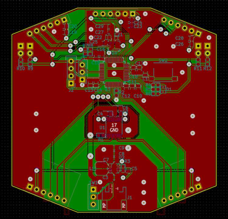
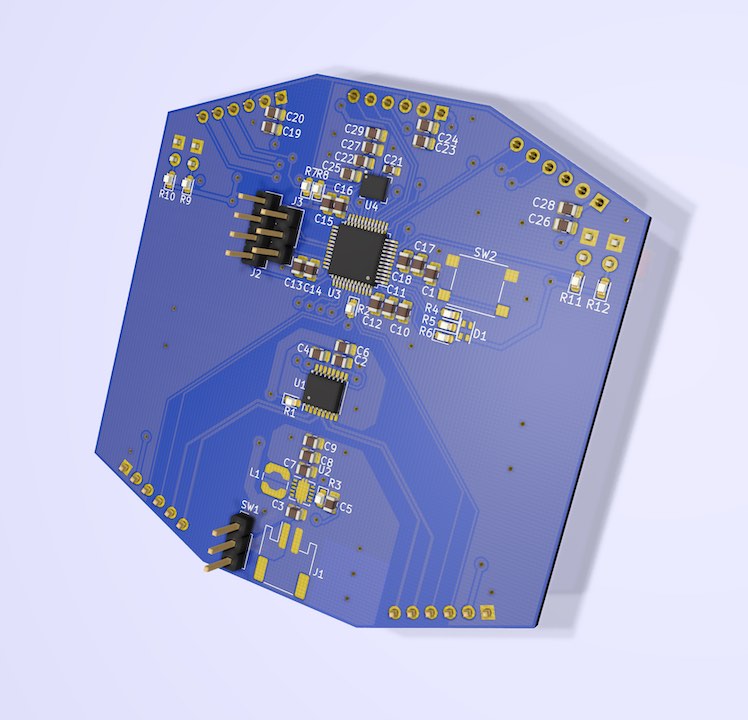
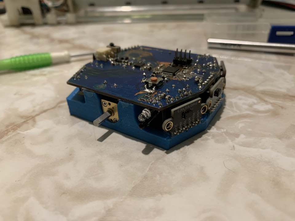
Aesthetically, I was going for a very symmetric look. Electrically, in testing I ran into issues with the VL53L0X failing after random amounts of time, which I at first attributed to noise. Thus I did my best to isolate the motor driver and reduce noise as much as possible. By placing the connector for the VL53L0X sensors directly on the PCB, I eliminated the need for much of the bulky wiring.
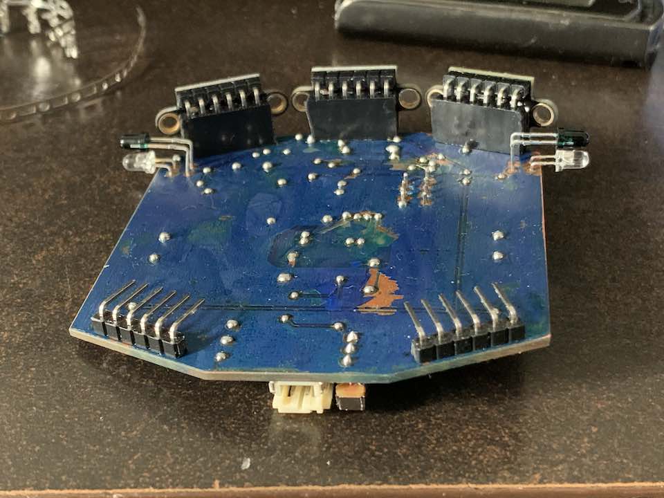
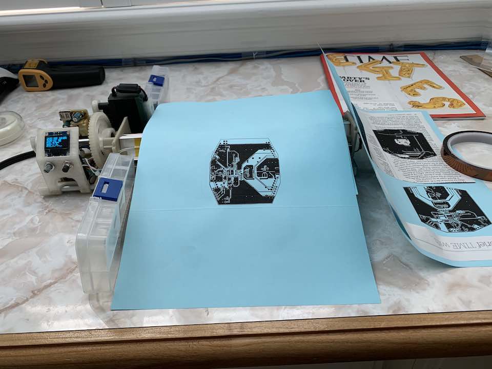
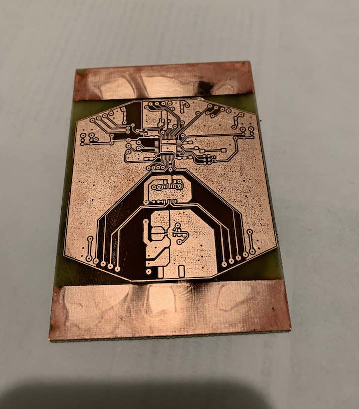
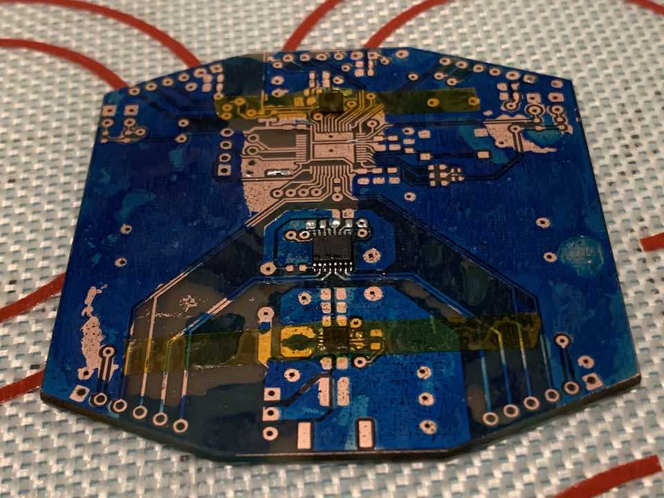
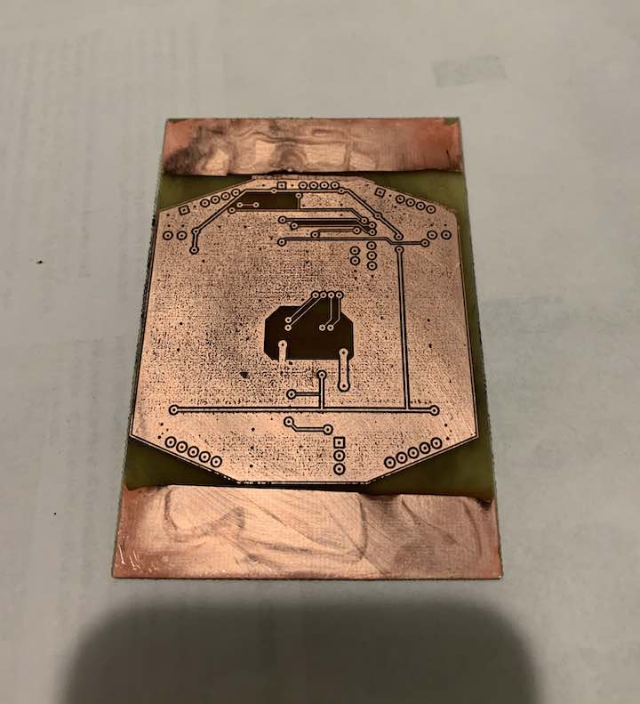
It took 3 tries, but I was finally able make the PCB. Due to its large size and double-sided nature, it is by far the most complex board I’ve made to date. The soldermask leaves a lot to be desired, but it works. As a one-off, this board is what I’d consider borderline between still making the PCB at home versus sending it off to a manufacturer.
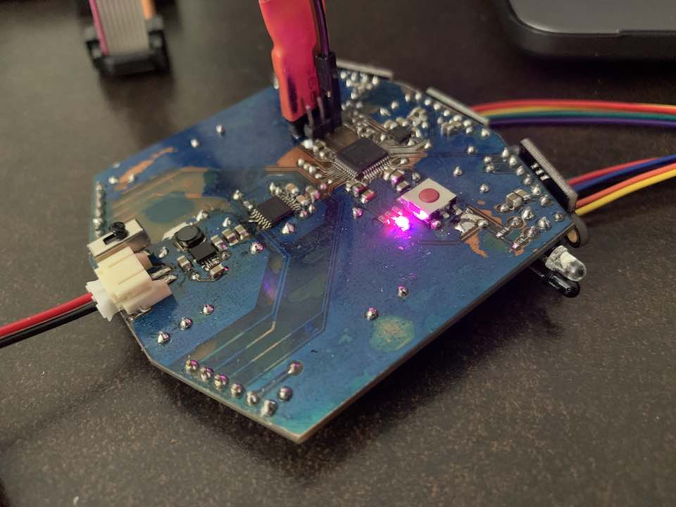
Some Bugs
Even with the noise reduction, the VL53L0X sensors still failed, marking the start of a long and tedious debugging process. First I tried removing the onboard LDO which actually turned out to be a 3.3v not 2.8v one, which could be a source of instability. These sensors can run on 3.3v so its fine. Then I noticed that turning off the encoder improved stability, so I heavily optimized my encoder library and that helped somewhat. By connecting an OLED display, I learned that when the sensors fail, the whole I2C bus is disabled. Unplugging the sensors made the I2C bus work again so I isolated the problem to the sensors. Then I found this website which advised removing the level shifter and that helped a lot but wasn’t perfect. Finally, I dropped the I2C speed to 125kHz again and everything worked perfectly. These sensors are cheap knockoffs from China, so I wouldn’t be surprised if they can’t handle 400kHz I2C.
To get the IR sensors to work, I used a 1MΩ pull-up resistor on the photodetector, resulting in a very high impedance output. When switching quickly between reading the left and right IR sensors, this results in one reading affecting the other. A simple fix is to just discard the first few readings.
A small issue I ran into was that the velocity readings from the encoder were very noisy. I was using X4 encoding which looks at every rising and falling edge of both channels. Switching to X1 encoding completely solved the issue. I guess this is because the A and B channels of these encoders are not a perfect 90° apart.
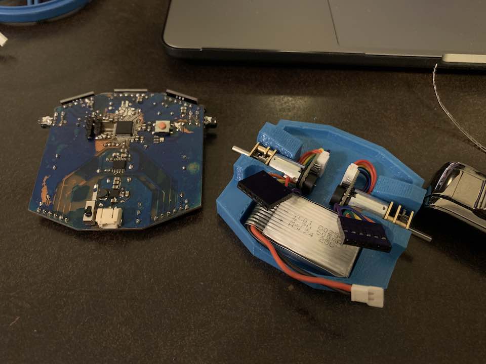
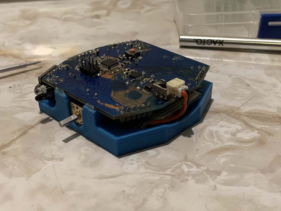
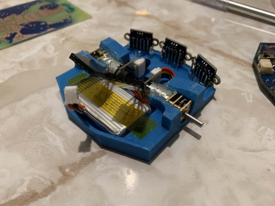
Putting It All Together
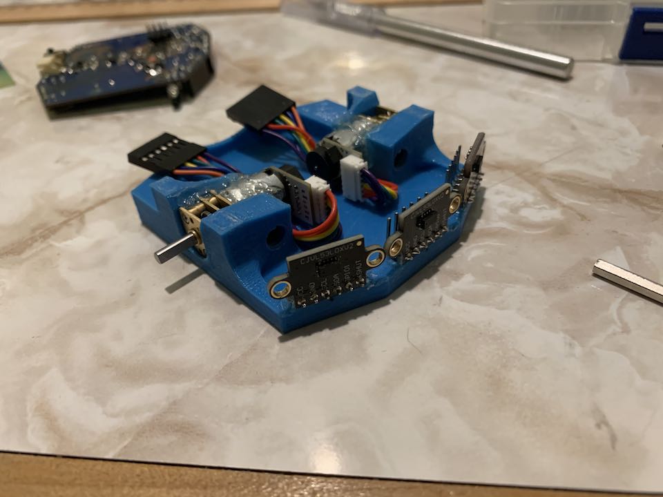
With all the electronics done and tested, I put together a CAD model to mount the motors and everything. Not having a caliper certainly did not help, but I got a decent fit.
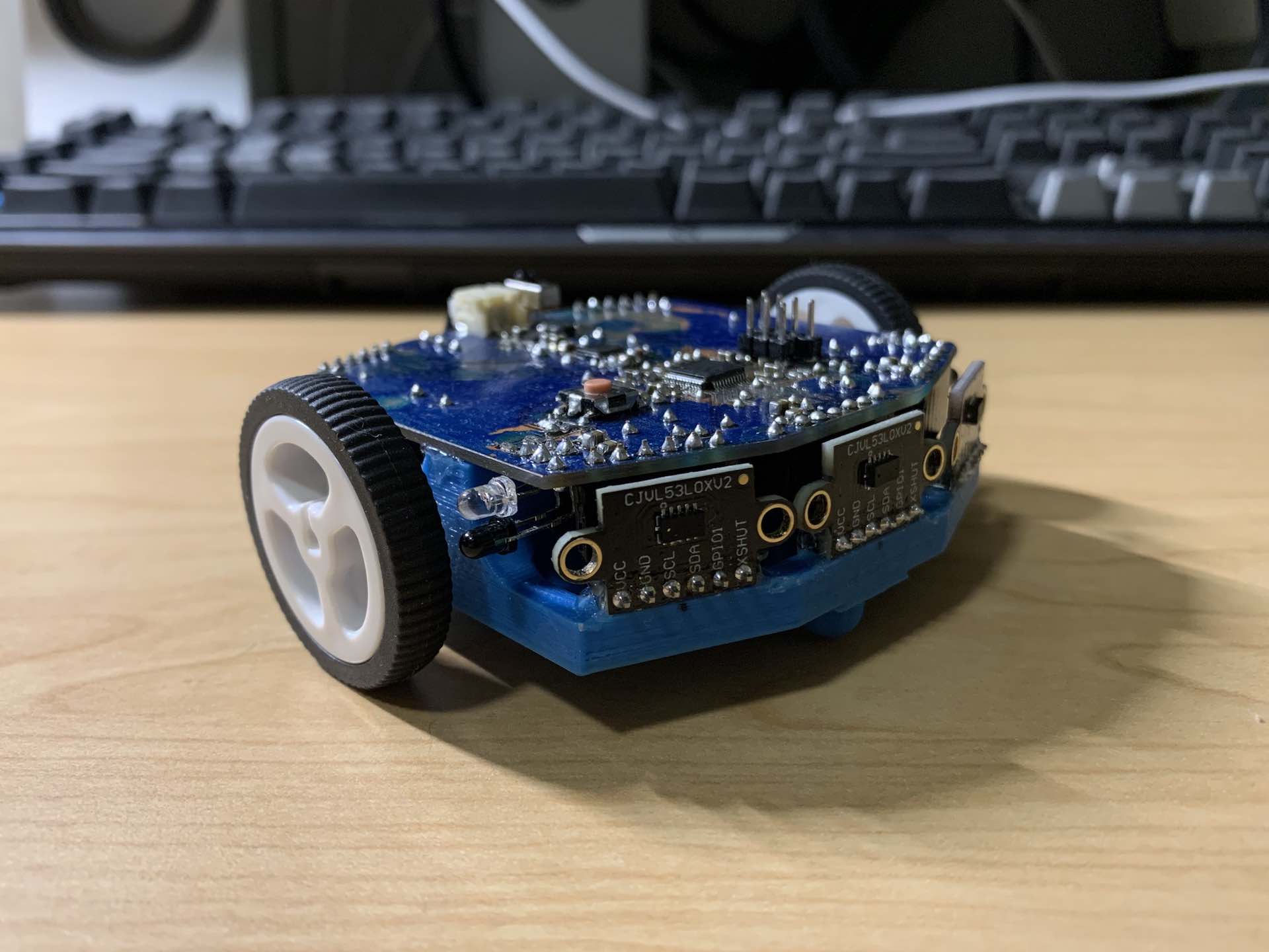
Overall, I really liked the design of my concept Micromouse and anticipate adopting a lot of its characteristics into our next generation of Micromouses when we get to it. There are quite a lot of things I’d like to change for the next revision. Here’s a somewhat exhaustive list:
- Professionally made PCBs w/ mounting holes and test points
- Add tactile switch for user to start maze finding
- Add MPU-9250 (Note it’s hand-solderable bc ground pad underneath is unnecessary)
- Switch to right angle female headers to make VL53L0X easier to mount
- Add vertical micro-USB port to open up DFU programming possibility
- Switch to 2S 7.4v LiPo and new regulator
Ready for the next revision!
Comments