
STM32 APRS
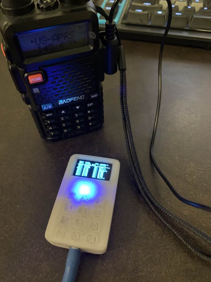
Back in July after having just gotten into HAM radio after taking EE123, I decided to build an attachment for my Baofeng UV-5R to allow it to transmit and receive APRS messages, something that’s usually reserved for more expensive radios. All of the code and design files are located in https://github.com/dragonlock2/STM32_APRS.
Algorithm
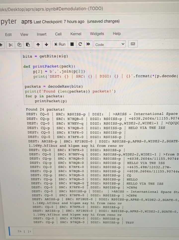
The part that I focused most heavily on was the modulation and demodulation algorithms for APRS packets. For fast development, I did everything in an iPython notebook first and slowly made adjustments to make it more C-like.
Modulation
We can split up the modulation of APRS packets into several parts. Let’s start with the packet format. All the information needed to specify an APRS packet are a destination address, source address, digipeater addresses, and up to 256 bytes of information to send. Addresses are specified as a callsign and SSID, a number from 0-15. The destination address is used to identify APRS packets and software version/application. The source address is your callsign and an SSID you pick. The digipeater addresses, up to 8, specify how far your packet can get repeated by stations around you, with WIDE1-1, WIDE2-1 being common.
To generate the bytes that need to be sent, we start by specifying how addresses are encoded, which you can find more info about here. Basically we need 7 bytes for each, 6 of which are for our callsign (padded with ASCII spaces if needed) and 1 for the SSID which occupies the bottom 4 bits of 0b00110000. We left bit shift each byte by 1 before we add it to our bytes to be sent. We add in our destination, source, and digipeater addresses all in that order. The LSB of the last byte we just added is set to 1 (the rest are 0 because of the bit shift) to mark the end of the addresses field. Then we add the control field 0x03, protocol ID 0xF0, and information bytes. Then we add in the 2 byte FCS field which is a CRC computed over all the bytes we just added. Finally, we prepend and append a couple of flags 0x7E that mark the start and end of the entire packet. Extra preflags give extra time to open up a receiver’s squelch and sync up the sample phase.
To generate the bits that will be AFSK modulated, we start by bit stuffing. For each byte to be sent, we add to our bitstream in LSB order and every time we see 5 ones, we add a 0. We specifically don’t bit stuff the flags which allows us to identify flags as anytime we see 6 ones in a row. The resulting bitstream is then NRZI encoded which basically means ones are encoded as keeping the same bit level while zeros toggle the bit.
Finally, we can AFSK modulate our final bitstream using Bell 202 AFSK. Basically, 1s use a 1200Hz tone while 0s use a 2200Hz tone. We transmit at 1200 baud, which means 1s get a full cycle while 0s get ~1.8 cycles. If we simply transmit a precomputed waveform for each bit without considering the bit that came before, we end up with phase discontinuities which increase our bandwidth. Since a different frequency just changes how fast the phase changes, we can keep track of the phase to compute the audio waveform and ensure it stays continuous.
For implementation on a microcontroller, I pretty much just rewrote everything to be line for line convertible to C. I tested frequently to make sure I didn’t mess anything up. For playback, I used a DMA transfer to the DAC peripheral at 38400Hz and a pingpong buffer. Since I already did most of the work and major optimizations in the iPython notebook, transferring to a microcontroller was very straightforward with the hardest part being learning how to use DMA for the first time.
Demodulation
To decode an APRS packet from the raw audio, let’s start with how we did it in EE123. I can’t seem to find the diagram we used in class but Stanford has a very similar one. Basically we pass one copy of the signal through a 1200Hz bandpass filter and another through a 2200Hz bandpass filter. Then we take the absolute value of both and subtract one from the other. We then sample at the right times to get the raw bits and then decode the bytes from there which I’ll go over later. This method appears to be the one used by Dire Wolf.
Since I was implementing this on a microcontroller, I was worried there wouldn’t be enough processing power to do it in real time. I came across the MicroAPRS project which runs on AVR processors and has a completely different DSP algorithm. I found this document from TI that does a good job of explaining how it works. Essentially we multiply by a time delayed version of the raw audio signal. Doing the math (left as an exercise for the reader) for both 1200Hz and 2200Hz, we get both a constant term and a high frequency term. A delay of 180° for 1200Hz, or 4 samples at 9600Hz sample rate, maximizes the difference between the constant terms. We can then apply a 1st order IIR low pass filter with a cutoff frequency of 1200Hz to get rid of the high frequency terms and keep our bits. I tried designing my own with SciPy and ended up with the exact same one as MicroAPRS’s. I also double checked it was stable. In practice, this algorithm works exceptionally well at a fraction of the computation, helping to decode as many packets as the bandpass method.
After this AFSK demodulation, we still need to choose where to sample at to get our raw bitstream. Optimally, we’d sample right in the middle of each bit period to maximize our chances of receiving the packet. However, our input signal will arrive with some phase shift which means we need some way to sync up with it. To do this, we use a PLL. There was a really nice diagram from EE123 which I can’t seem to find, so I’ll try to explain it in words. We start with a signed counter that increments and overflows at 1200Hz. We want to sample a bit at every overflow which means bit transitions happen at zero crossings for our counter. To accomplish this, we nudge the counter back to 0 every time there’s a bit transition in our signal. If we nudge by too much, our phase tracks minute jittering in the input signal. If we nudge by too little, our phase doesn’t track the input signal phase well. Multiplying by 0.5 works pretty well in practice.
After applying the PLL, we have a raw bitstream that’s still NRZI encoded and bit stuffed. We can do the NRZI decoding pretty easily by just checking if the sampled bit matches the previous sampled bit. The bit unstuffing and gathering of the APRS packet bytes is done using a state machine. The state machine starts by looking for the bit sequence 0b1111110 which denotes a start flag. Then we switch to a gathering state and store each bit, ignoring stuffed 0s, until we hit an end flag, where can finally decode the packet if the number of bits gathered is the right size. Decoding the packet involves first checking the FCS, control field, and protocol ID and then grabbing the appropriate fields.
For implementation on a microcontroller, it was again pretty straightforward as I wrote everything to be as C-like as possible. My favorite bit was in the LSB implementation of the BitFIFO which means I could literally grab the underlying uint8_t array for packet decoding once the bits were gathered. As usual, I did frequent testing while doing the Python to C-like Python conversion. The data acquisition was done using DMA from the ADC peripheral at 9600Hz and a pingpong buffer. I was initially worried the computation would be too heavy to do in real time, but it ended up consuming only 2.5% of the CPU.
Software
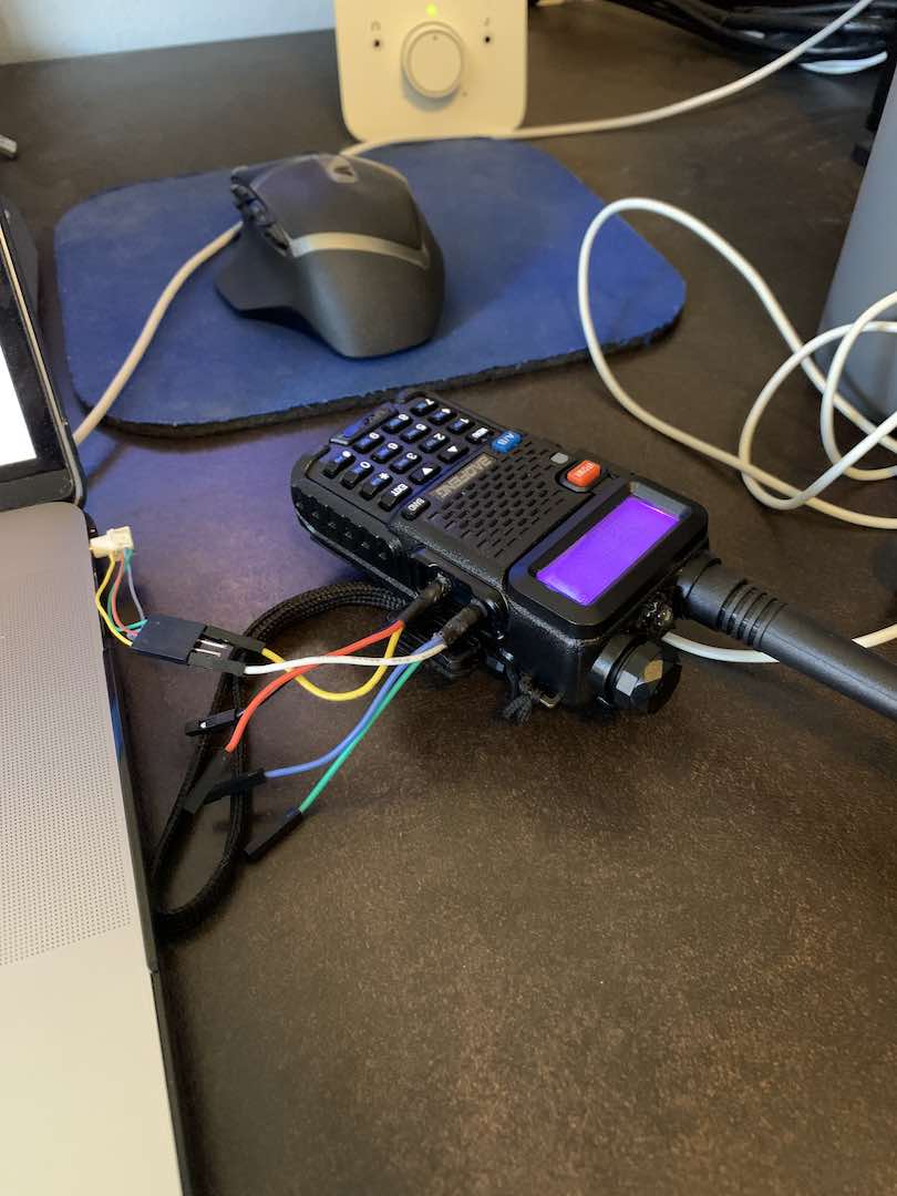
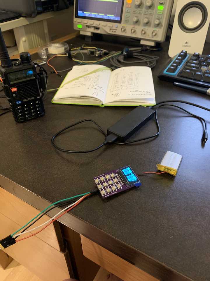
Due to the sheer number of unknowns and firsts that I would need to accomplish with this project, this was the first time I actually completed most of the software before even designing a PCB. I’ll go over the hardware decisions in the hardware section, but this is pretty much what my desk looked like for the better part of a week or two.
Here’s all the different modules and layers of abstraction I developed to get the whole thing working. The running theme was to use DMA and perform computation in interrupts as much as possible so that all the main function had to do was call some high level setup functions and then do whatever it wanted from there.
BitFIFO/IntFIFO
This was the first thing I worked on since it was fundamental for the APRS algorithm. It’s pretty simple just a ring buffer implementation of a queue which was one of the first things we learned in CS61B. I attempted to do some kind of inheritance from a common interface since I needed one FIFO for bits and one for ints, but C doesn’t make it quite as straightforward.
APRS/AFSK
I already went over the bulk of the APRS algorithm above, so I’ll just go over some more details in the microcontroller implementation. The AFSK module handles modulating and demodulating an AFSK signal using DMA. The idea of the pingpong buffer is that we perform our DMA transfer on one half of the buffer while performing computation on the other half. ST makes this really easy with its half transfer complete callbacks and a cyclical DMA transfer. The APRS module then handles converting to and from the useful data contained in each packet.
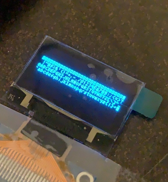
SSD1306
Starting from Adafruit’s SSD1306 library and the datasheet, I proceeded to build the driver for STM32. I wasn’t satisfied with just copying Adafruit’s library and instead strove to understand what each line did. My library isn’t quite as fully featured as the Adafruit one, but I’d say it’s good enough for the majority of use cases. When getting the DMA setup, I wondered why an interrupt based transfer wasn’t the same thing. After digging through the code, the interrupt transfer actually calls a callback after every byte is transferred to start the next byte which means it isn’t a CPU-free transfer. I should’ve used a pingpong buffer, but in practice the effects of writing to the frame buffer as it’s being displayed are barely noticeable.
To maximize the amount text I could display, I looked for the smallest legible font I could find. I eventually came across a 3×5 one (4×6 with spacing) that worked. It’s interesting to note how the Adafruit library stores fonts as bytes and as such can directly write each byte to the frame buffer rather than pixel by pixel. The tradeoff is that fonts have to be a multiple of 8 pixels tall. Since I wanted the smallest font possible, I had to write my font pixel by pixel.
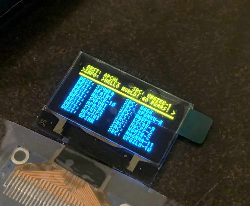
APRSGUI
Designing a fully featured UI for such a tiny display was quite the challenge. Safe to say I have a lot of respect for people who do this kind of thing. I ended up with something that could display the message to be transmitted as well as the 8 most recent messages. Since the entire message can’t fit on one line, I added text scrolling as well as blinking cursors to indicate there’s more info to see. Lot’s of tweaking and debugging later, I had something that I’m pretty proud of.
At 24 FPS, rendering the UI takes up a whopping 50% of the CPU. Since I was doing the rendering inside an interrupt, I made sure to set its priority lower than the one for the APRS algorithm.
Keyboard
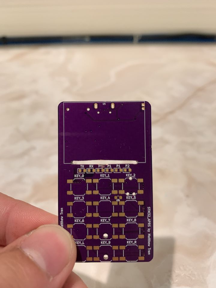
Since I gave myself the deadline of finishing the project before school started in August and I was still busy with an internship, I couldn’t source the BlackBerry keyboard in time which was what I originally wanted to use. With only buttons in my parts stock and quite large ones at that (PTS 810s were too thick for what I wanted), I eventually settled on a T9 style keyboard from the flip phones of days past. To be able to enter any ASCII key, I used the same method as flip phones where pressing a key multiple times in succession allowed entering different characters. I added multiple “pages” to keep the maximum length of these sequences short. I also tried to keep the mappings as intuitive as possible, to the point where I can somewhat type messages despite blank keys.
Interfacing the keyboard module with APRSGUI was simple since I designed APRSGUI to take in ASCII characters as commands. I did have to modify APRSGUI to be able to display the character about to be entered for some user feedback.
Hardware
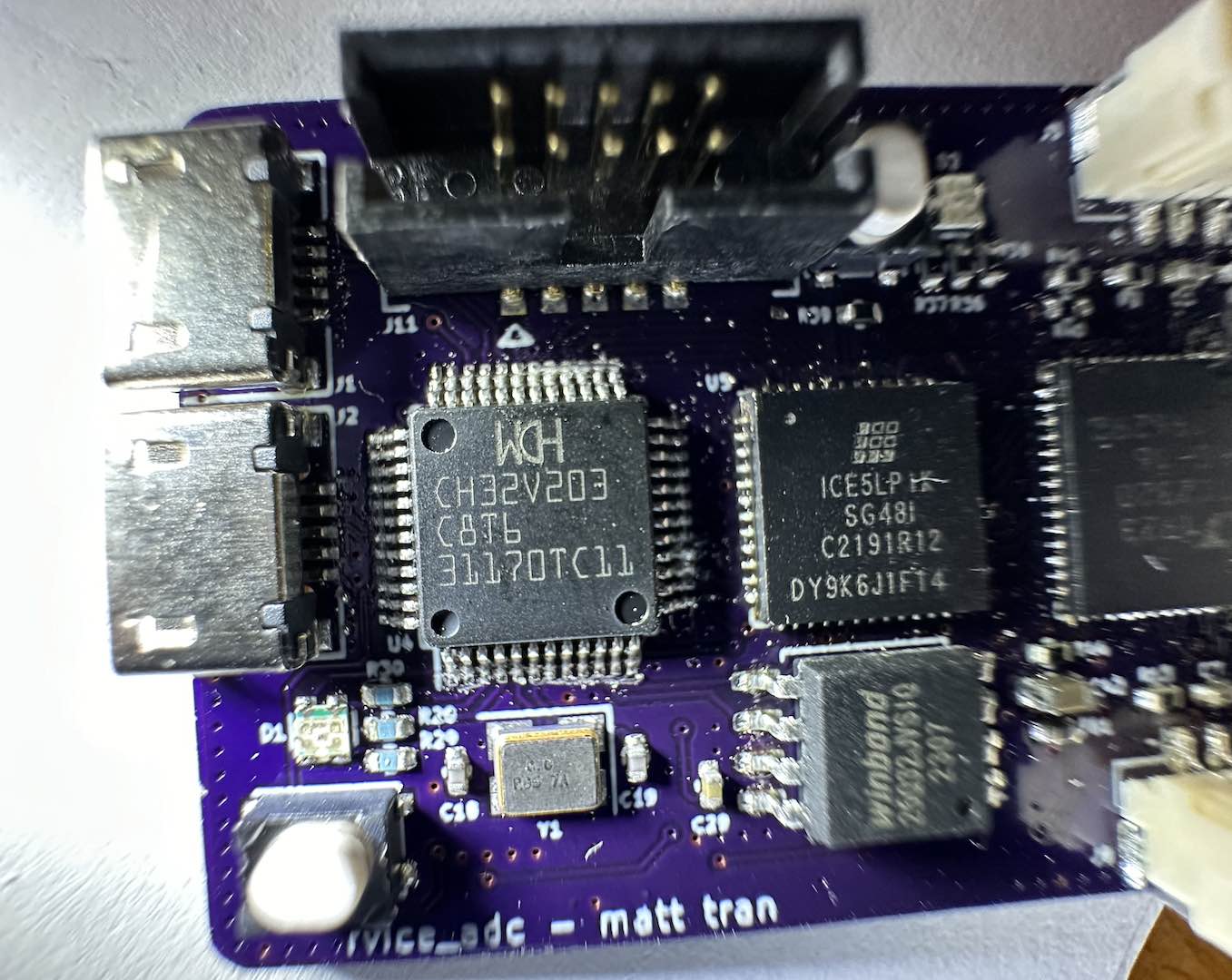
With the algorithm complete, I could start designing the actual hardware. I chose to develop on the STM32L433CCU6 simply because I had some samples of it and was initially worried I didn’t have enough computational power. In retrospect, a Cortex M0 would probably suffice.
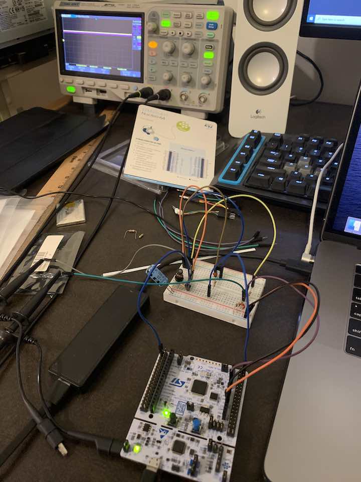
Since I worked on the software first, I had to breadboard everything. I had so many issues when transmitting since the USB debugger kept resetting from all the noise. Measuring on the oscilloscope, the Baofeng spits out quite a bit of noise over its audio lines when transmitting. This reminded me of one of the labs in EE123 where even on low power with an attenuator and shielding the Pi inside a metal box, the audio chip kept glitching out. In hindsight, it was probably the excessive noise coming in through the audio lines that caused this issue.
Before I was comfortable transmitting on the national APRS frequency of 144.390MHz, I started on an unused channel. Funnily enough, I accidentally transmitted on one of the weather channels which is illegal for HAMs. Thankfully the FCC didn’t come after me. This is what happens when you start studying for your HAM exam the day of and after almost pulling an all nighter. I passed, but I forgot things.
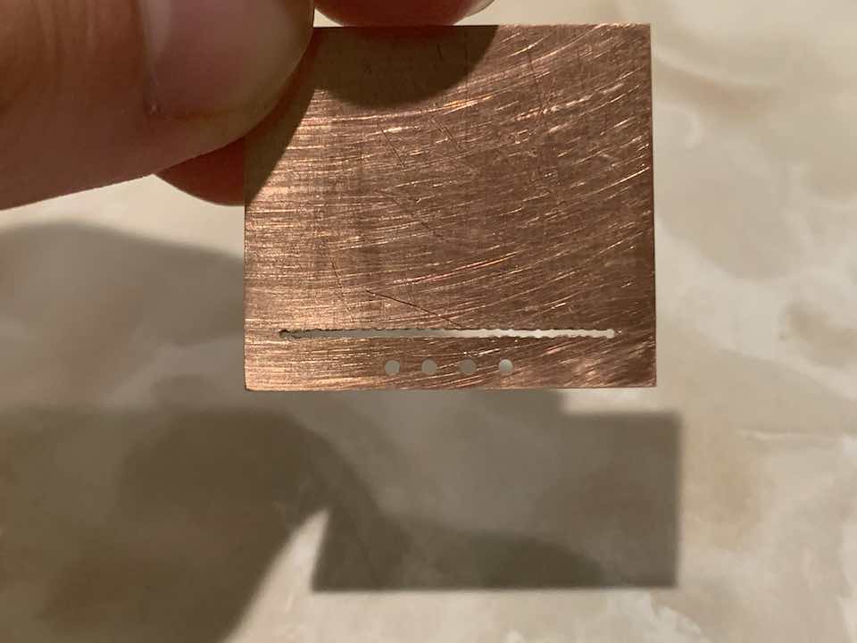
Since this was the first time I would be using the raw SSD1306 OLED module in a project, I built a little breakout board first. KiCad didn’t want to do the slot drill, so I had to write a little script to attempt it.
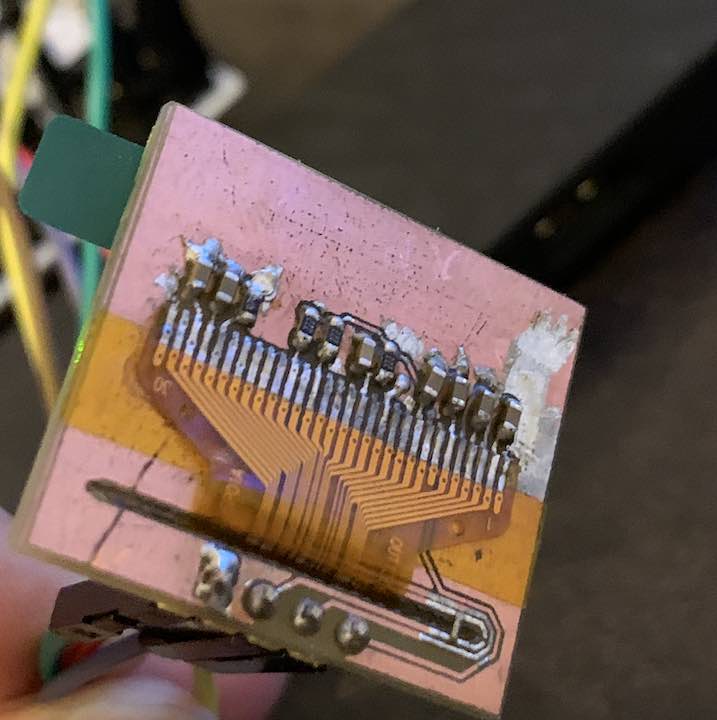
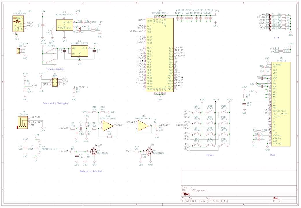
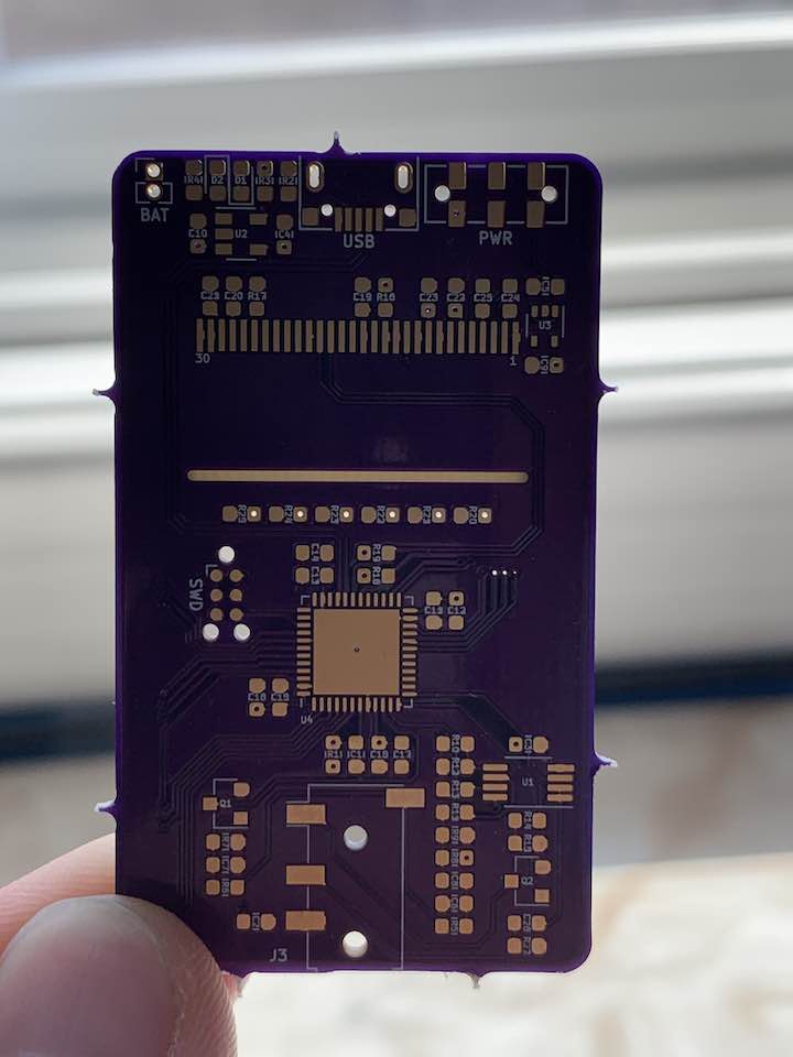
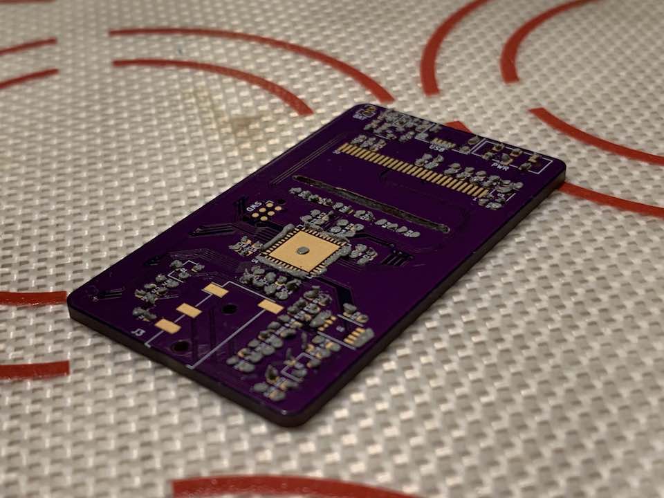
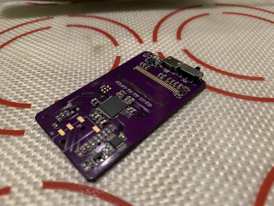
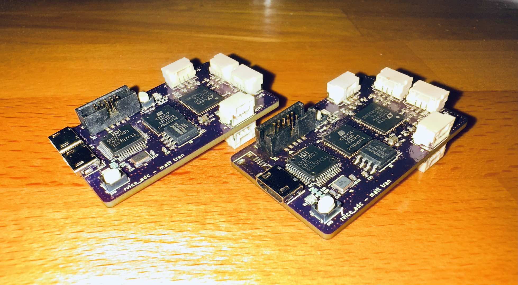
Once that worked, I was finally ready to design the final PCB. Most of it was pretty straightforward and just involved throwing a bunch of standard components on. In hindsight, the SSD1306 supporting components or layout need adjustment since I can’t hit 1MHz I2C on it. I also need to adjust the decoupling caps or add more filtering since enough noise still gets through to distort the DAC, which was a huge issue I had during development. I don’t have much experience with analog frontends, but what I designed works pretty well.
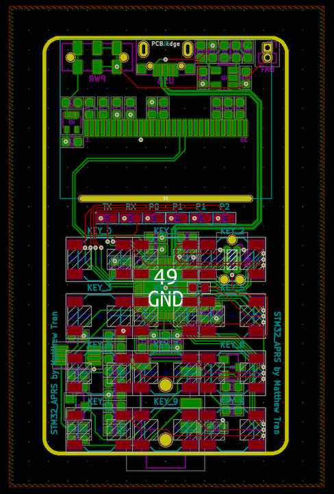
The PCB layout was pretty straightforward as usual. This was the first time I routed a differential trace in KiCad. It doesn’t have the right differential impedance, but it works. In hindsight, although a 6 mil trace width on the power lines is sufficient, I should’ve made it thicker because I accidentally shorted the battery through a trace in testing and burned it.
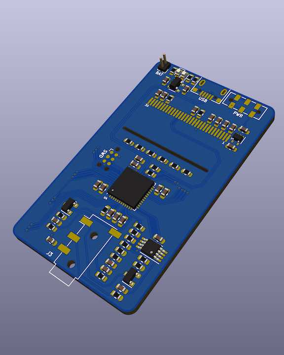
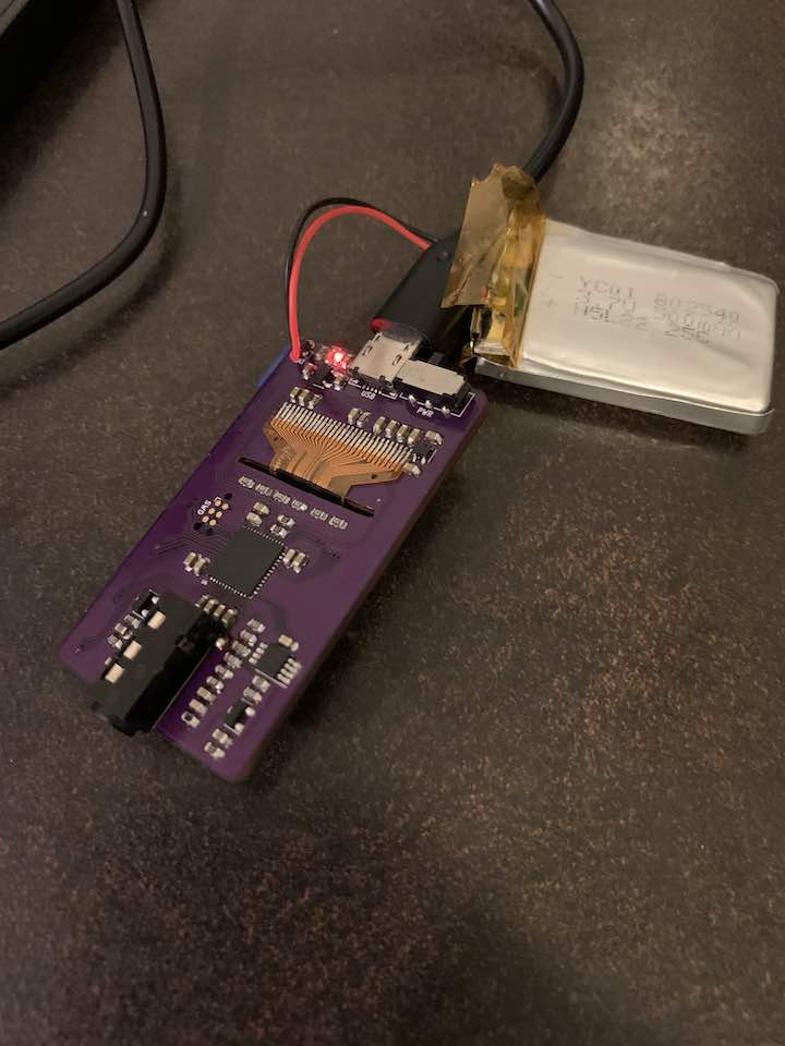
OSH Park, my new go-to PCB manufacturer, did a great job with the PCB. They actually failed to manufacture the super thin and long slot for the SSD1306 the first time around, but they refunded me and got it the second time. Since school was about to start, I couldn’t wait for the second board run and actually took a Dremel to the defective board to cut the slot and was able to get that to work.

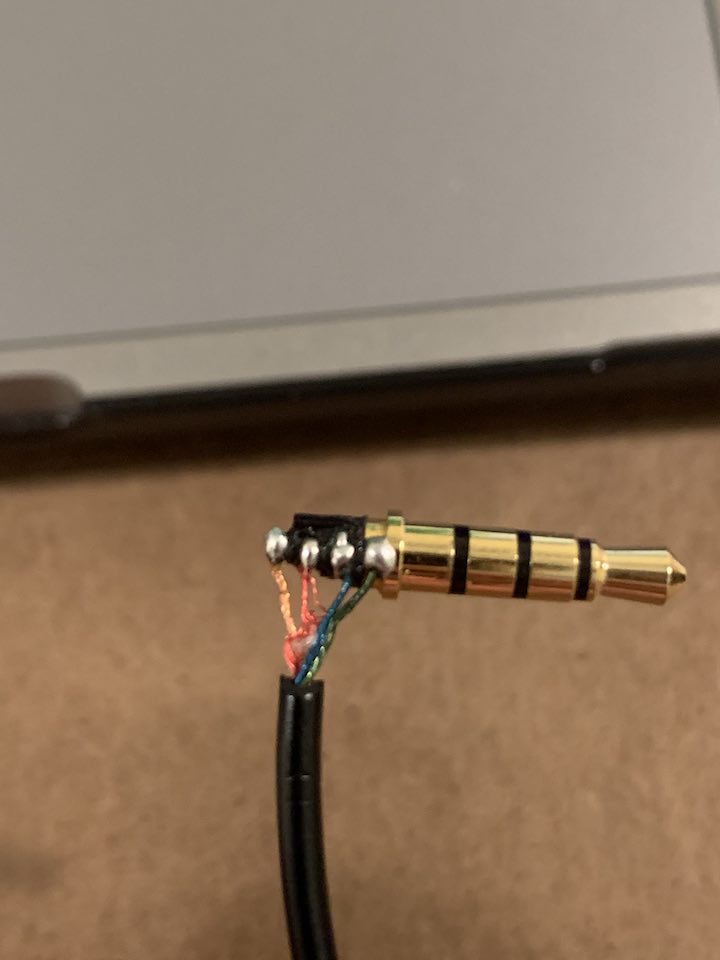
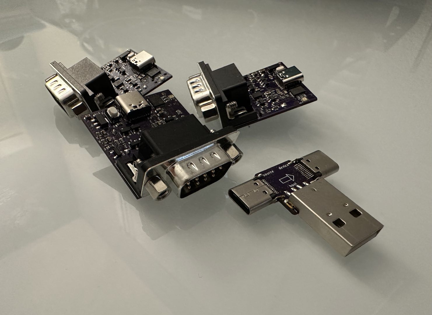
This is what happens when you buy the cheapest TRRS plug on Digikey.
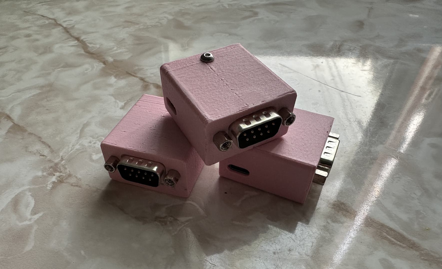
As usual, toss on a custom 3D printed case and half an hour of sanding and it looks great!
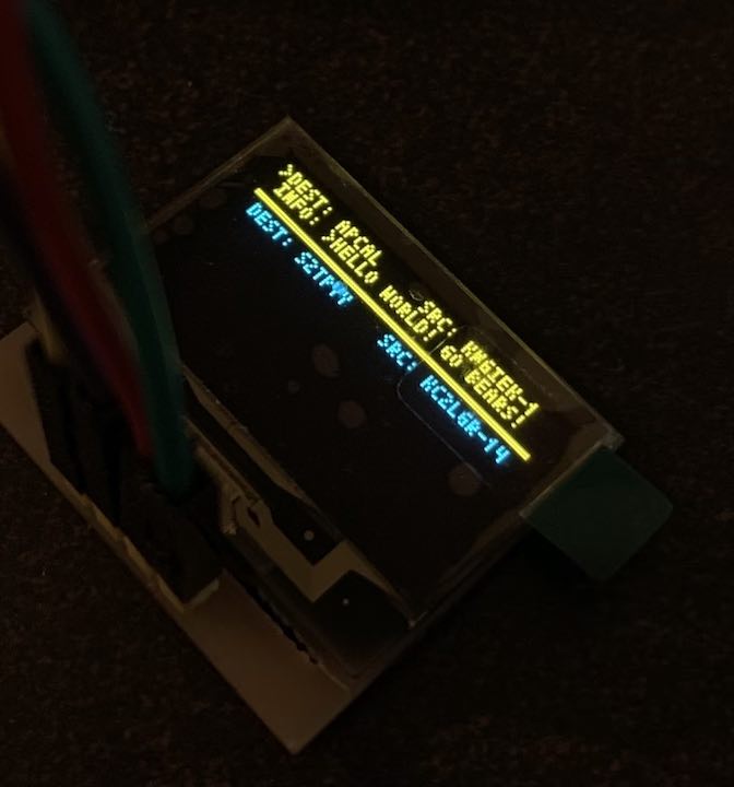
Demo
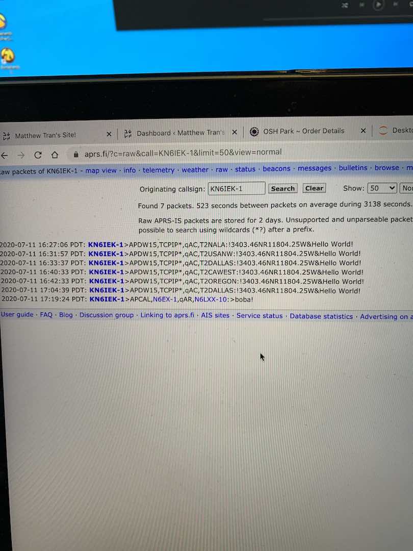
Overall, this project turned out pretty good. There’s definitely a good number of improvements to be made, in particular on the audio frontend. I can’t seem to get transmissions between handsets to work probably because there’s just too much noise and distortion. The IGates in LA and Berkeley pick it up fine though. If I ever get around to another revision of this project I’ll make sure to iron those bugs out.
Comments