
6wire
https://github.com/dragonlock2/kicadboards/tree/main/projects/6wire https://github.com/dragonlock2/zephyrboards/tree/main/samples/6wire
After being in industry for a bit, I learned about the 6-wire measurement technique. The idea is clever yet simple and enables accurate measurement of components in-circuit despite it being in parallel with other components. It starts with a standard 4-wire (or 2-wire) meter placed across the DUT. For every alternate current path, we place a two wire “guard” at a node along that path that drives the voltage at that node to the same as one of the DUT leads (depending on architecture). Of course, we could also use one wire merging both feedback and current driving, but that comes with the same drawbacks as using a 2-wire over a 4-wire meter. Since both nodes share the same voltage, no current flows along that path and the 4-wire meter just sees the DUT. This idea can be easily extended to more alternate current paths.
Design
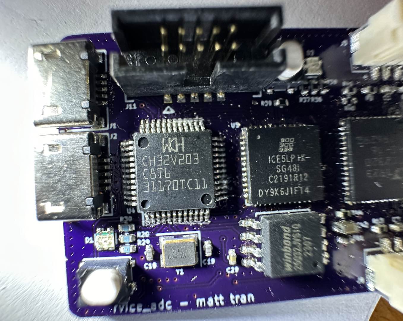
Since I came up with this idea two years ago, I had already ordered many of the chips I would need in this project. I wanted it to be auto-ranging so I got several precision resistors and a MAX4639 analog switch. Thankfully I got the double-pole model which made the architecture viable.
An important factor in the 6-wire guard performance is the accuracy with which the nodes’ voltages match. This necessitates a low input offset voltage (and low input bias current for large resistance measurements) op-amp so I got the industry-leading MAX4238. Thankfully I got the one that was stable down to unity gain.
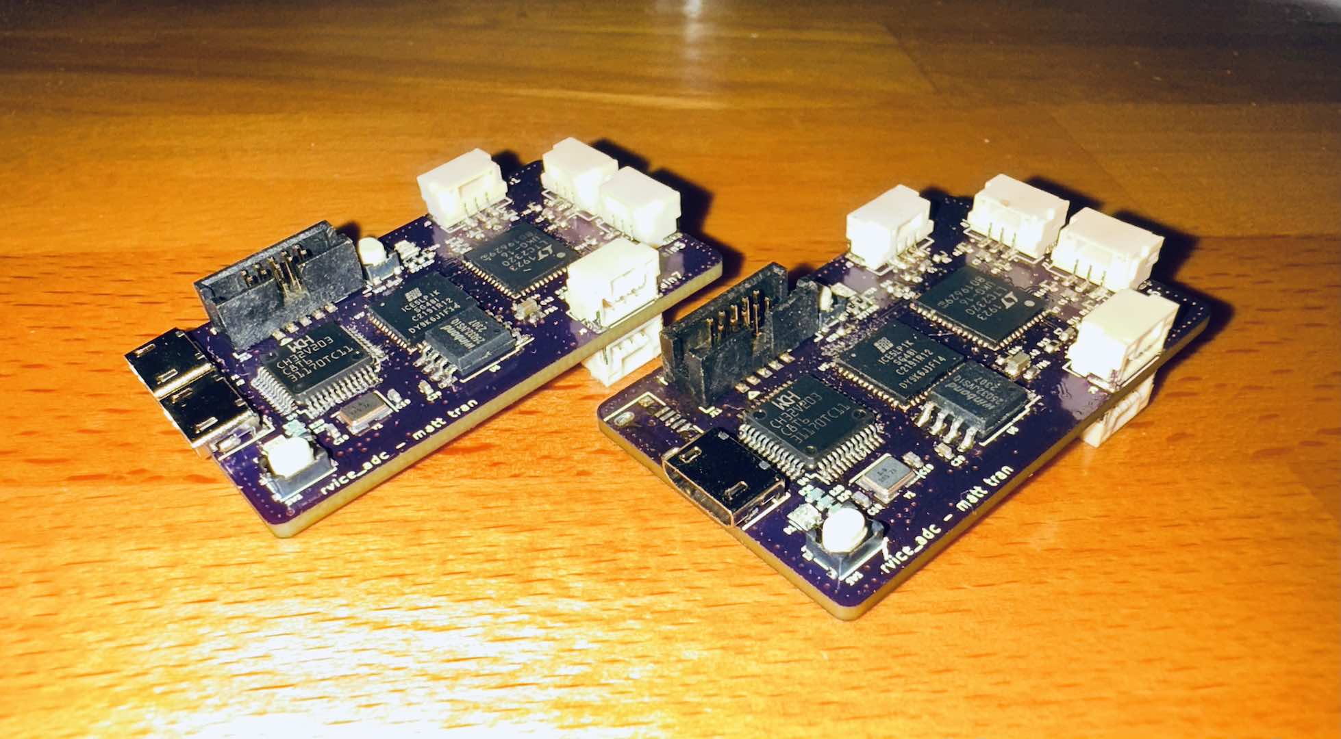
For the 4-wire meter, I decided to use the ADS122C04 24-bit ADC which can take differential measurements and reference voltages. I used the ratiometric ohmmeter architecture from the app note. Since I had reference resistors from 10Ω to 10MΩ, I needed to make sure that everything was within specification across that range.
To ensure the 10Ω 1/8W resistors I used wouldn’t overheat, I created a ~100mA current source with a standard op-amp and PMOS. I didn’t have any smaller resistors for current measurement, so used another 10Ω one. I initially set the current lower, but had to increase it due to an issue discussed later. While I could’ve done a low-side current sink with an NMOS, I didn’t due to the 10Ω reference resistor which reduced the voltage budget I needed to meet the other ADC input voltage requirements.
For maximum resolution across the range, I made sure to support the internal PGA in the ADC. The main constraint was that the analog inputs had to stay below a certain voltage (~2.7V for my use case). There’s also minimums, but I was well within those. As such, I effectively created a voltage regulator with a standard op-amp and PMOS. I was initially worried about PMOS leakage currents causing issues with the 10MΩ reference, but based on rough estimates it was going to be fine.
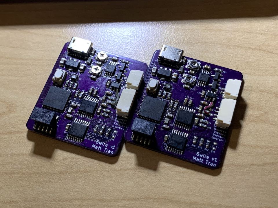
The layout ended up being pretty straightforward once I came up with an organization that separated the analog and digital domains cleanly. It was also my first time doing a Kelvin connection! I admit my analog noise design and layout skills aren’t great, so I’m sure there’s much to be improved. Based on the good but lower than expected ENOB measurements I ended up getting, this is definitely the case.
Firmware
When writing the firmware, I ended up having quite a bit of fun messing around with the features of Zephyr. I really like interrupt or thread based drivers that don’t require the application code to constantly call a function. Thus, I made the ADC do continuous conversions and send GPIO interrupts that I would then use to increment a semaphore that enabled a thread to run. The auto-ranging algorithm was also interesting since I had to consider different reference resistors and gains while also making sure I converged on the right selection quickly due to the low 20Hz sample rate of the ADC (chosen for maximum ENOB).
Since I used a ATSAMD21G16B with 8KB of SRAM and 64KB of flash, I initially had issues with RAM usage. Zephyr is not exactly known for a small memory footprint. Everything was fine until I added the USB CDC serial driver, so I started by looking into its memory usage. It had some ring buffers which I shrank. Then I realized a lot of memory was potentially taken by stacks for various threads. After scouring the compiled Kconfig for stacks to shrink, I shrank each one until the code stopped functioning. At the end of the day, I barely fit everything within 8KB.
Results
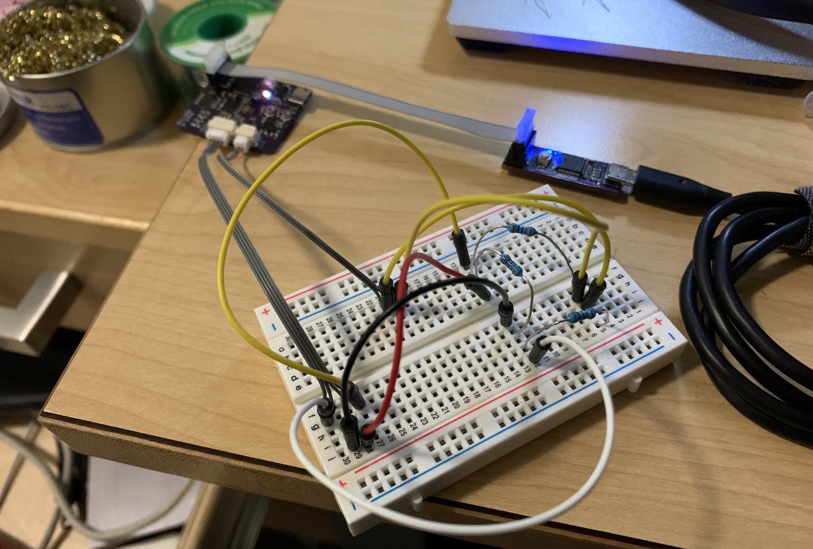
Once the 4-wire ohmmeter section was working, I started testing the 6-wire guard feature. It initially didn’t work, with the measurements being thrown off despite the node voltages matching. After looking at the schematic again and pondering for awhile, I realized a crucial mistake. With the circuit using Vsense+ as the guard reference, the extra current it sources also flows through the reference resistor but not the DUT.
After even more thought and slight panic, I had a simple solution. While Vsense+ is used in the NI diagram, using Vsense- is just as valid and would be considered its “dual”. Rather than source current into the low side to equalize node voltages, the guard sinks current from the high side. This ensures that the DUT and reference resistor see equal current. Since I have a high-side current source, this would “steal” current from the DUT. As such, I increased the limit from 80mA to 100mA to minimize this effect.
Thankfully, the change could be realized with a trace cut and bodge wire. With that, everything worked!
Comments