
STM32 ESC
https://github.com/dragonlock2/kicadboards/tree/main/projects/stm32_esc https://github.com/dragonlock2/zephyrboards/tree/main/samples/stm32_esc
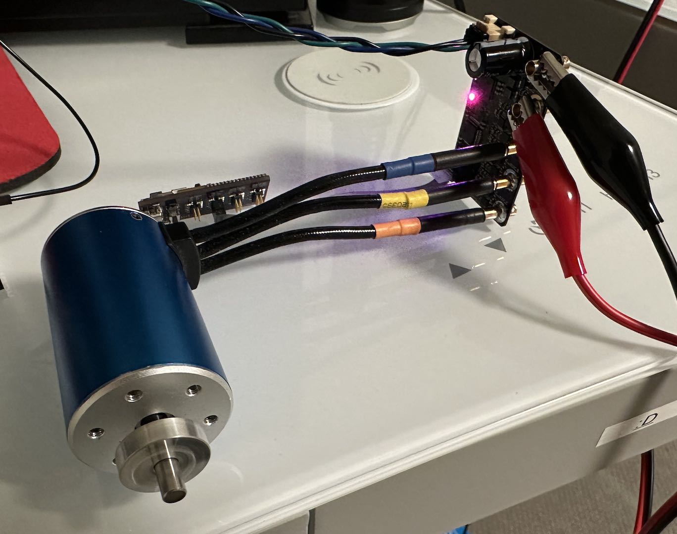
After using off-the-shelf ESCs for so long, I decided it was about time I learned the algorithm and hardware design behind driving them. While sensored control is quite easy, I stuck with a sensorless design for cost. While I eventually want to try sensorless FOC, I made sure to start with the far simpler and common sensorless trapezoidal control scheme.
The power part of the hardware was relatively straightforward with only three PWM-able half bridges needed. By using an ATA6844 which has shoot-through protection as the gate drivers, I ensured that burning my board would be difficult. The sensing part was where things got interesting and quite unclear. Drawing from several open-source designs, the first method was using 3 comparators to compare each motor terminal against the average of them all to find the BEMF zero-crossing. The second method was cheaper in terms of parts and involved measuring the motor terminal voltages directly and computing the zero-crossing in software. The last method was for FOC and added current sense to two half-bridges (I did three for simplicity). Wanting to maximize success, I did all three methods.
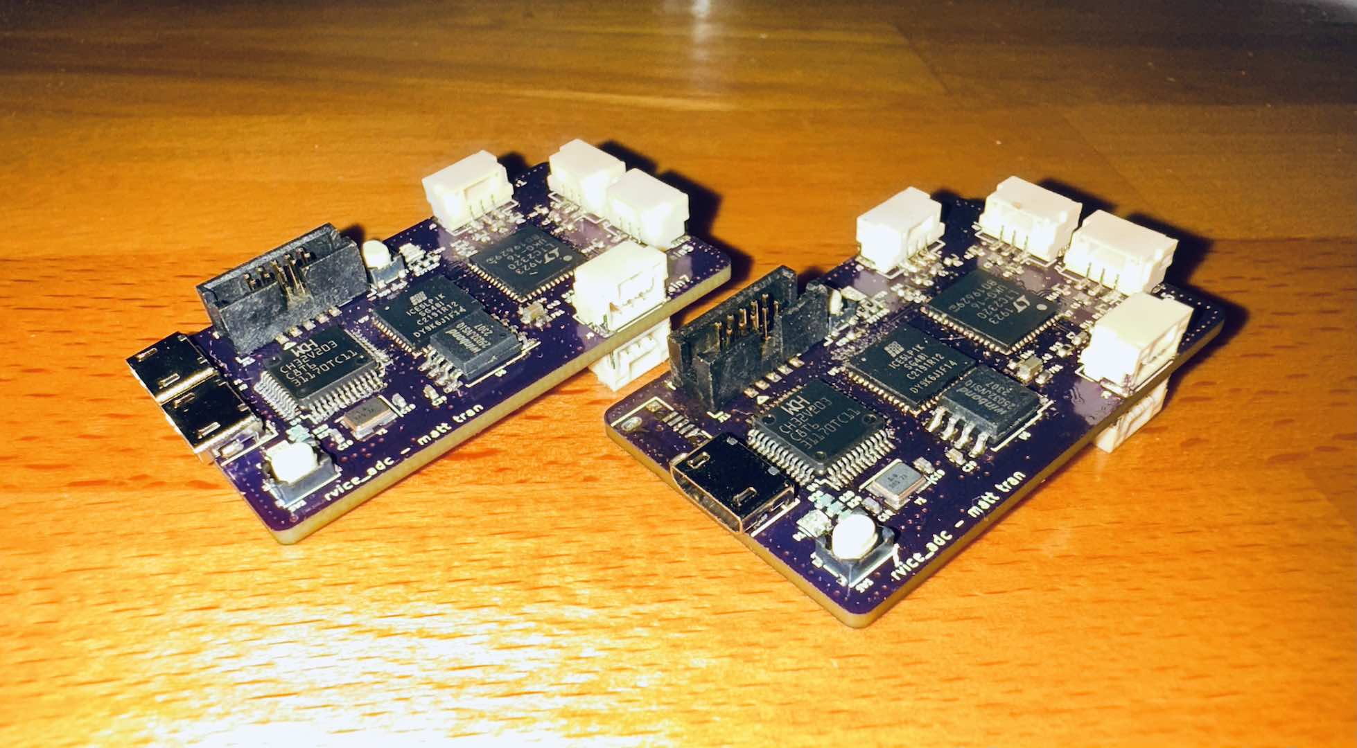
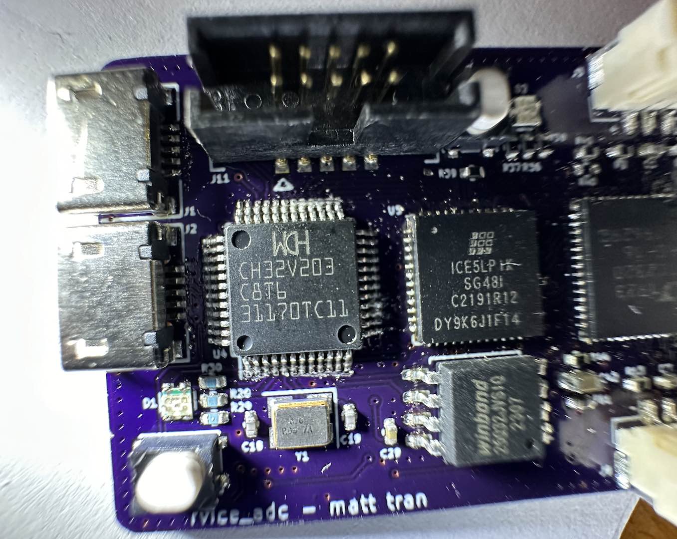
There’s not much to say about the layout other than the hell I went through keeping everything in two layers and all the parts on one side. The board is a bit large, but I got it.
The firmware was surprisingly straightforward and I even got it working in Zephyr. After fixing the UART driver to get LIN working, I brought up the gate drivers. I started with open-loop control and just sequenced through the six steps of trapezoidal control. For closed-loop control, I made the important note that the zero-crossing edge direction we’re looking for depends on the previous state of that pin (either + =>; HiZ => – or – => HiZ => +). Before getting to try it, my hard drive motor broke leaving me with only a high speed/power BLDC. With a resistance down to the 10s of mΩ, messing up would likely result in a burned FET. While initially hesitant, I eventually took a leap of faith and just tried it. It worked!
After working out some open-loop parameters to get the motor spinning fast enough for closed-loop to take over, I moved everything to be interrupt based. One important thing to note is that going to the next trapezoidal step has to happen at 30° from the zero-crossing for optimal switching. This was accomplishable with a Zephyr timer (after increasing the resolution). After thinking about synchronization issues, I settled on the motor control loop running constantly even at zero PWM and new PWM/direction requests coming over a message queue. By adding a timeout to waiting for a BEMF zero-crossing that automatically switched between steps, motor startup became straightforward. Closed-loop was defined as seeing all the BEMF zero-crossing interrupts for at least a few revolutions. While it may not be the best way, it certainly worked.
Last but not least was adding a LIN interface. Based on the cycle times, the interrupt rate is pretty manageable, triggering at worst every 100us (makes sense based on the motor parameters).
Overall, this project was a success. In the future I may look into FOC or even removing the RC filters on the BEMF detection (VESC does this by synchronizing the ADC and PWM). I could even drive the FETs more directly, but then I’d have to worry about shoot-through and PWM dead time.
Comments