PCB Laminator
Written 8-22-19
One of the things that I have never been able to get working reliably has always been homemade PCBs. Over the years I’ve tried basically every method in the book. For projects that need multiple copies of a board or are quite complicated and compact, sending it off to a manufacturer is both time and cost effective. However, generally speaking a single sided board with 7 mil trace and space is good enough for most prototyping needs. The fast turnaround time for a DIY PCB is also unbeatable. With my furthered exploration into all things surface mount, it became even more imperative to come up with a reliable method of PCB manufacture at home.
Other Methods of PCB Making I’ve Tried
Toner Transfer Method (Clothing Iron)
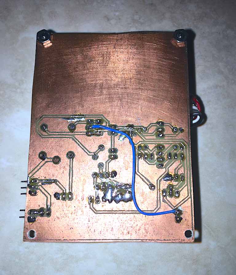
I started trying to make PCBs back in sophomore year of high school. Initially, I tried the ever so popular method of using a clothing iron to transfer toner to a copper clad board. I had far more failures than I had successes. It’s really difficult to get the perfect combination of temperature and even pressure. The issue was really the human component. Still, it was enough to get by until I had something better.
CNC Milling
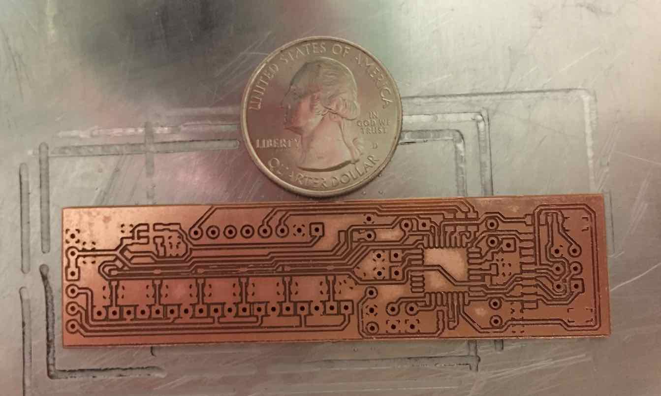
Coming into senior year I was working more with SMD components so I definitely needed a reliable way of making PCBs. Using the CNC router I recently built, I tried milling my own boards. It was actually pretty reliable for a time, but I kept on breaking end mills and every time I messed up a board it’d waste a lot of material. Even more, while FR2 boards were reliably millable, the traces don’t adhere very well and the board’s heat resistance is poor. FR4 is a much better choice for my purposes, but it’s much harder to reliably mill.
Hybrid Mill and Etch
I ended up developing my own hybrid mill and etch method to reliably make FR4 PCBs. It also allowed me to go from a 12 mil trace and space to 8 mil. The method involved covering the board in Sharpie and then milling away the Sharpie and some copper if I could. Afterwards I’d throw the board into the etchant to get rid of the rest of the copper. This method was really nice because I didn’t have to drill any holes myself or cut the board to size. It also solved the issue of breaking end mills because I would never go too deep. And if I was too shallow, the etchant would just remove the rest of the copper.
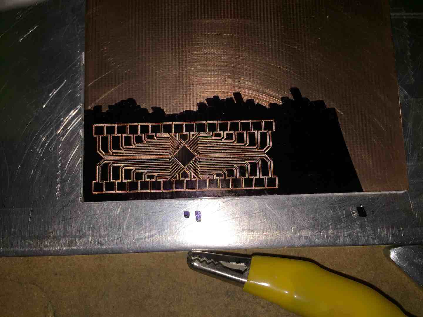
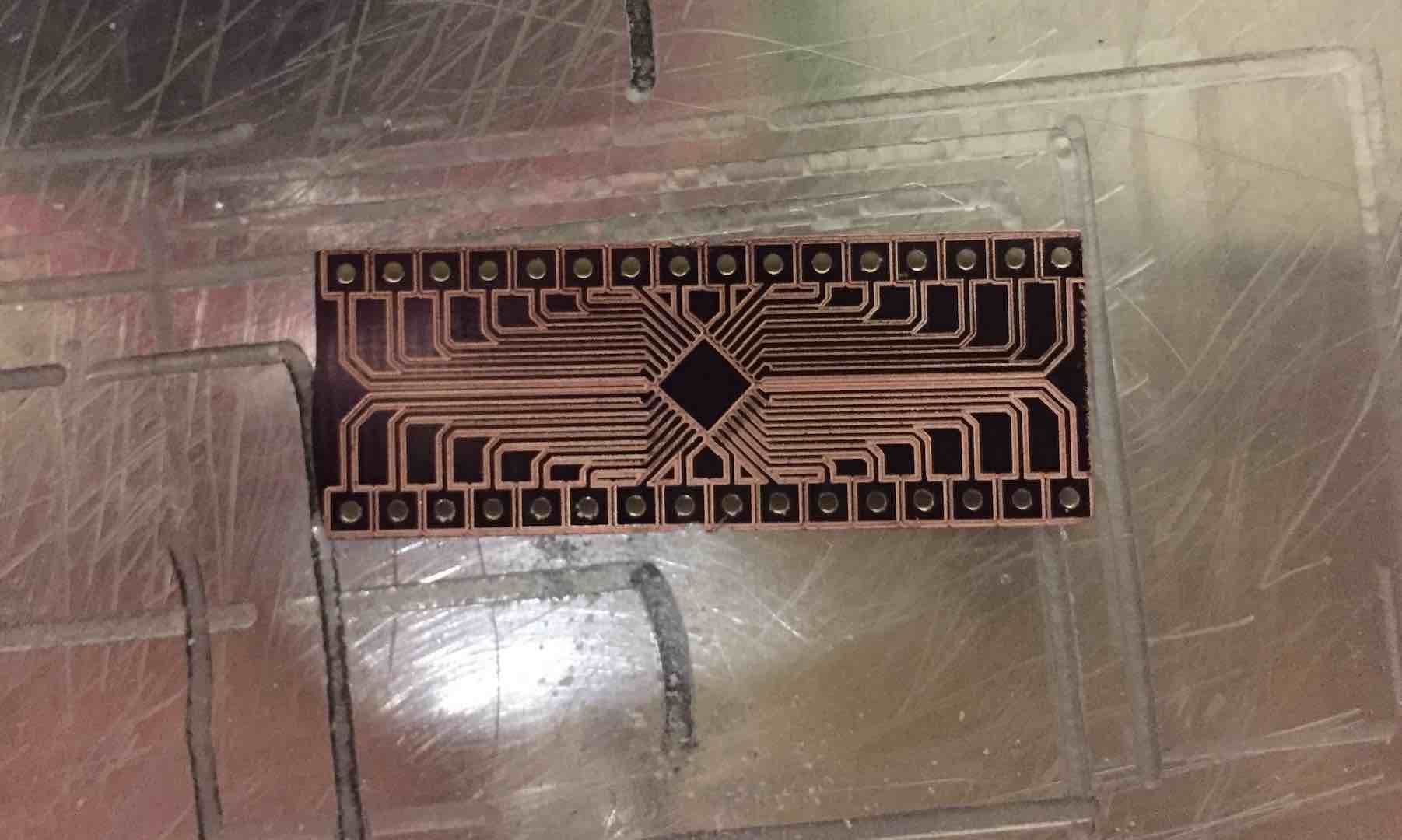
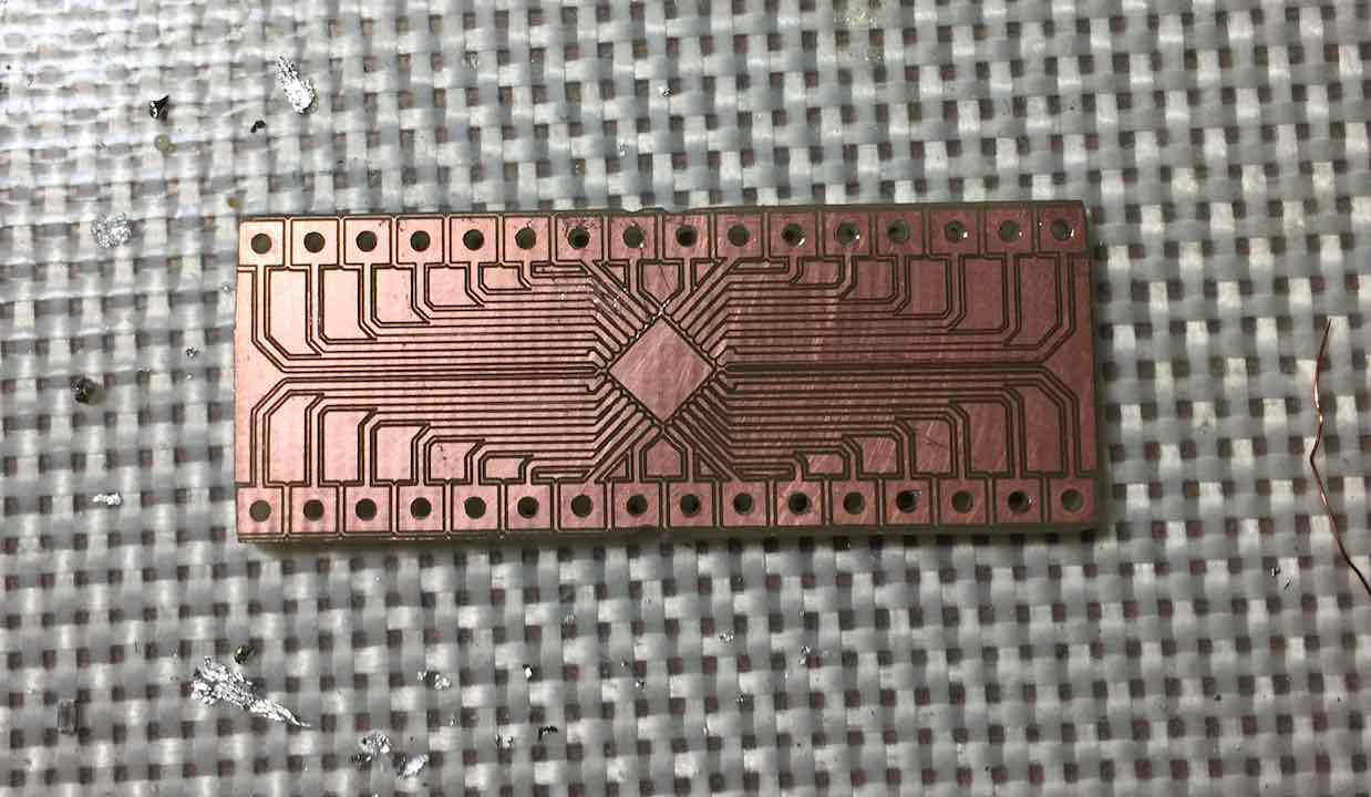
Overall, it was tedious, but very reliable.
Conclusion
I also tried the no heat transfer method which involves pouring a mixture of acetone and isopropyl alcohol on top of the toner to dissolve it and transfer it to the copper. Safe to say it did not work. One method that I heard about that supposedly works really well is using a photoresist, but I didn’t want to try it because it could get expensive.
After all my attempts, I was still in search of a better method. I refined my requirements quite a bit. Most of all it had to be reliable and precise enough to make 8 mil trace and space FR4 PCBs. It also had to remove the human component in any areas that needed consistency. Another thing is cost and turnaround time. Getting the raw materials had to be widely available (e.g. Amazon) and cheap. The last thing that would be really nice is to be portable. Lugging a giant CNC router around is not portable.
PCB Laminator v1
A couple weeks into winter break, I decided to give PCB making another go. I really liked the concept of the toner transfer method because of how simple it was. I just needed a machine to do the actual transferring. Doing more online research, I found out about people using off the shelf laminators to make PCBs. Having both high consistent pressure and even temperature application, it was the perfect method.
There’s pretty much no good how-to on making a PCB laminator, but the concept is pretty simple and widely applicable. The gist is to take a laminator and modify it to control its temperature and feed rate. Technically, people have gotten the method working without any modifications, but I liked having the fine adjustments. First, I had to choose a laminator and since I wanted one that was cheap and easy to find, I went with the AmazonBasics laminator.
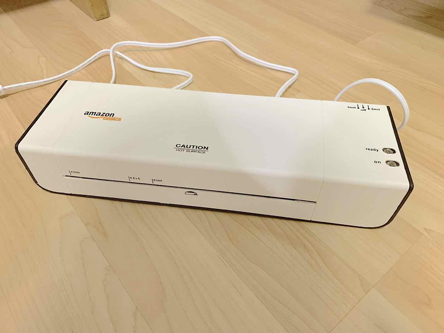
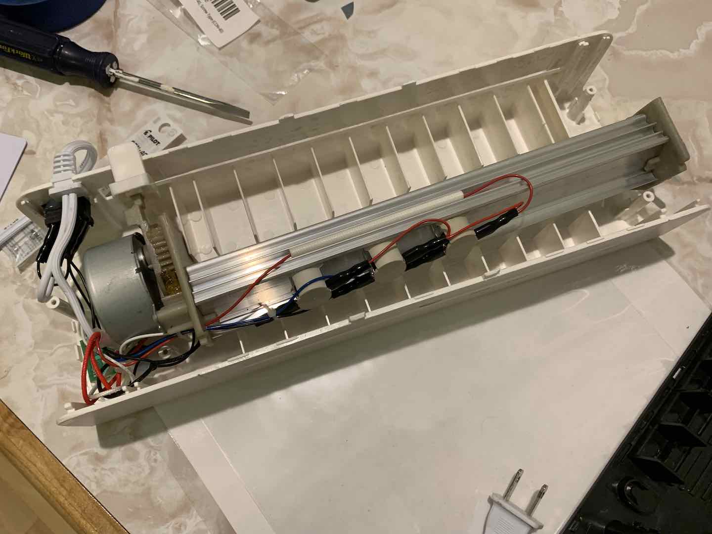
Taking it apart, I noted the relatively simple construction. Since I would be working with small boards, I’d have to either heavily modify the case or completely ditch it altogether to have closer access to the rollers. The heater would be pretty simple to turn on and off and the thermistor would be placed where the temperature controlled switches originally were. The one part that proved a challenge was getting fine control of the rollers using the existing AC motor.
I immediately got to stripping the electronics to just the heater and motor. I tried to learn how to reverse and slow down the motor but got nowhere. As a workaround, I ended up just turning the motor on and off at set intervals to get the speed I wanted. With the control systems worked out, I immediately got to soldering the electronics together. Since I couldn’t yet make PCBs easily, I used all THT components.
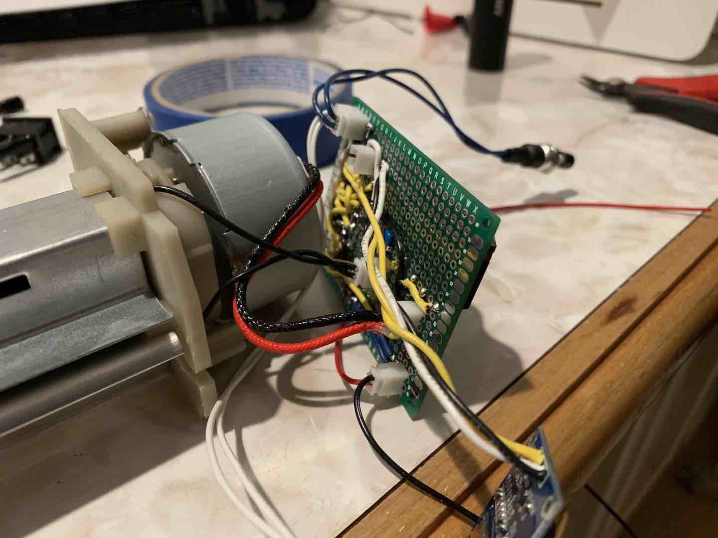
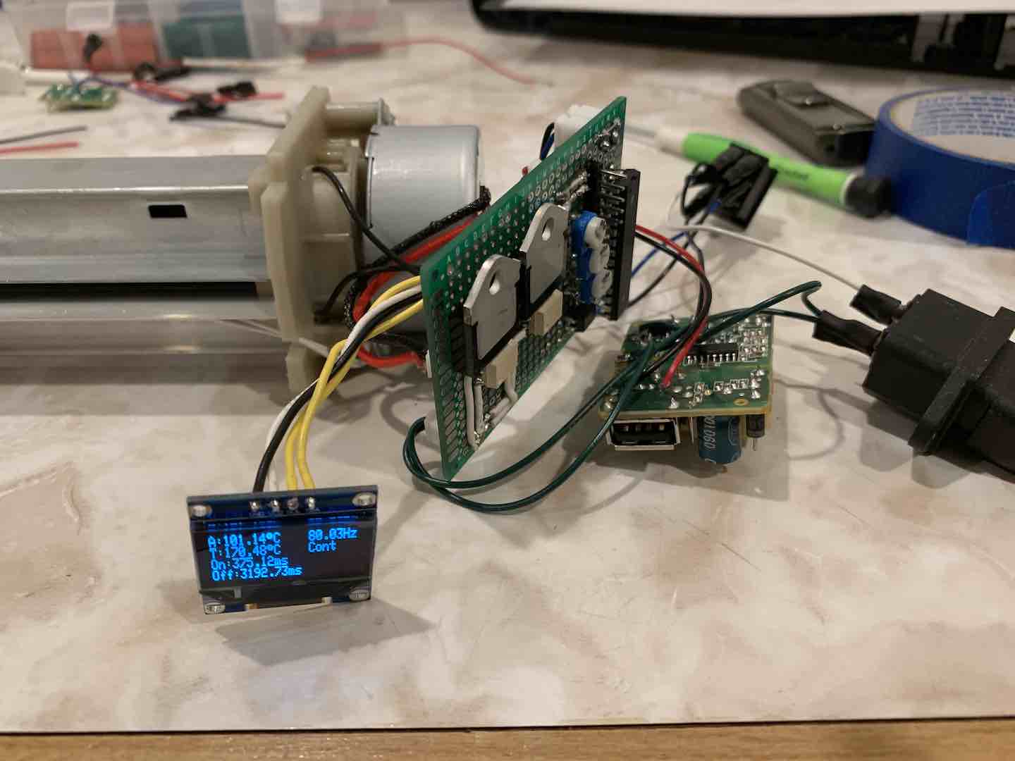
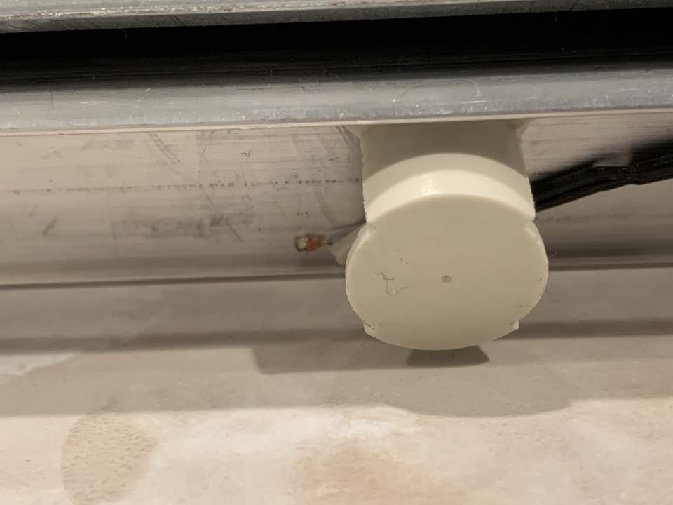
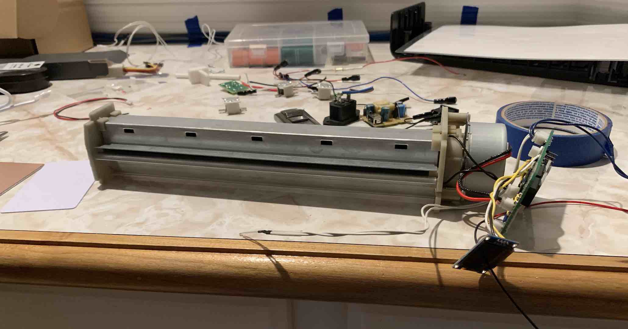
For controlling the AC components, I used BTA16-600B TRIACs with MOC3021 optoisolators. There’s also a zero crossing detector so that I could turn things on at a zero crossing, reducing strain on the TRIACs. I used a little snubber circuit on the motor TRIAC to correct for the inductive load. To power the microcontroller, I used an off the shelf USB charger. Some potentiometers and an OLED display would serve as the user interface. The main safety concern was the loose wiring and exposed AC power lines, but considering this was just a prototype, it was fine for the time being. Also, I was pushing the JST-PH connectors to slightly above their limits. Funnily enough, I didn’t have any heat resistant tape at the time, so I jerry-rigged the thermistor mount.
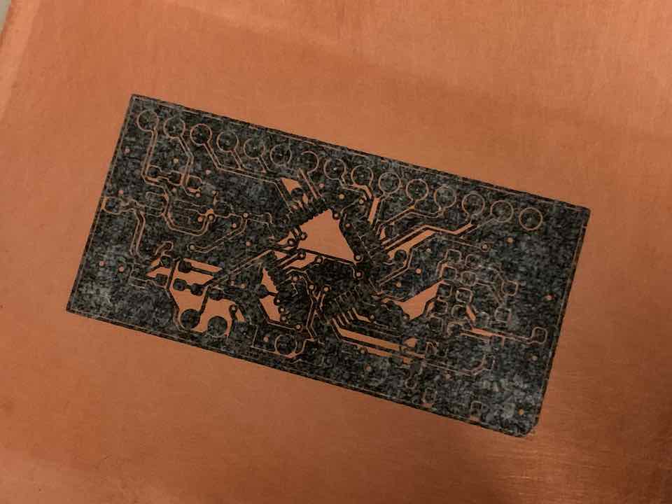
Overall, this prototype did not work very well if at all. The main issue was motor control. It didn’t respond well to being turned on and off all the time and would often get stuck. Also, it appeared that having a constant rolling pressure worked better, but since I couldn’t reverse the motor I had to stand there constantly watching the machine. Even more, the user interface I designed ended up being really clunky. Well, it was nearing the end of winter break so I had to set the project aside for the summer.
PCB Laminator v1.5
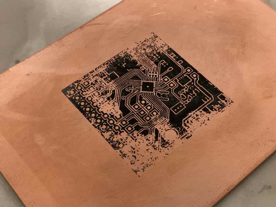
Coming back in the summer I immediately got to work on revising my prototype. I started with attempting another transfer using the v1 hardware and I actually got a pretty decent result.
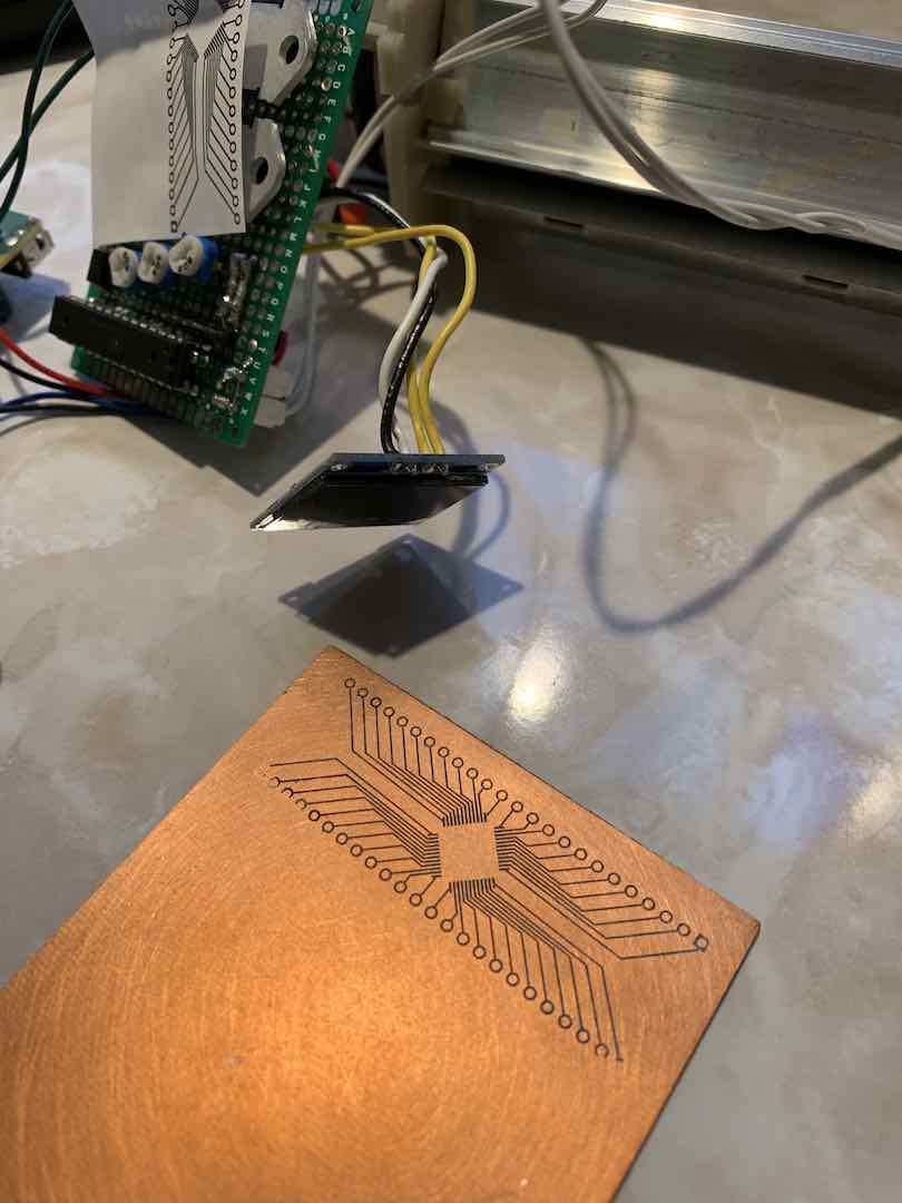
Seeing that the method was viable, I continued on with the project.
Motor Control
First, I had to solve the issue of motor control. I knew I had to ditch the AC motor that came with the laminator. I needed something that was easy to control, reversible, and in my parts bin. Initially, I considered using stepper motors, but none of the controllers I had used 5v and I didn’t have a small 12v brick so that wasn’t an option. The next choice was a servo or Vex motor. I had a bunch of Vex motors lying around and didn’t want to mess around with servo horns so I ended up picking the Vex motor. What’s really nice is that Vex motor controller 29 provides a cheap and easy way to control any DC brushed motor. I just had to make a slight modification to bypass the 4.5v linear regulator.
Mount and Gearing
The first thing to do was mount the motor. In order to prevent the heat from the rollers from melting any of my 3D printed parts, I made sure that anything that interfaced with the rollers was heat resistant. The main point of concern was the gear that meshed with the gears that drove the rollers. Luckily, one of the included gears had an 8mm ID, which meant I could connect it to a ubiquitous 8mm steel shaft. I cut a keyway into both the gear and shaft to fit a metal key and maintain a tight fit.
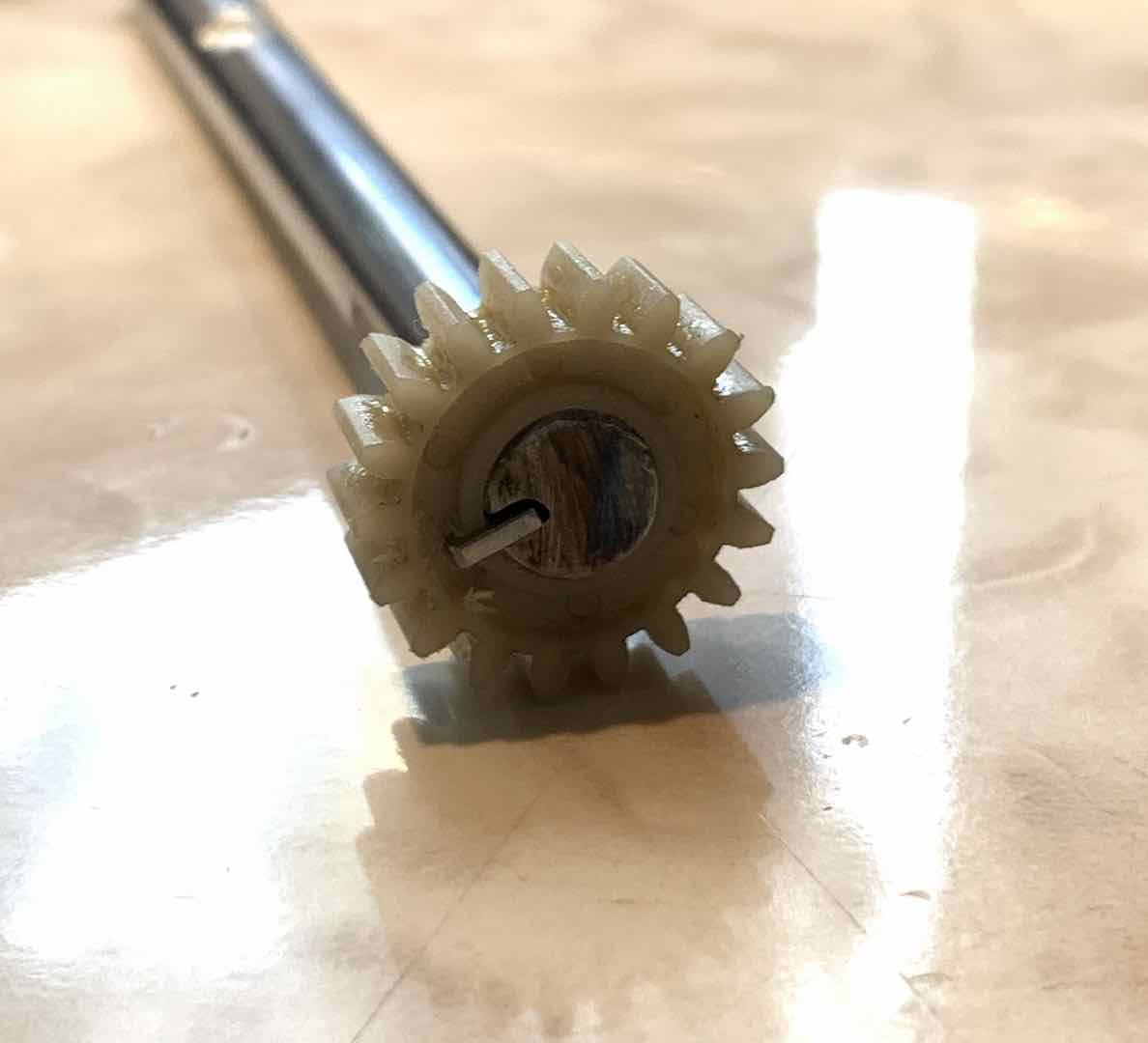
With that done I had to bring everything into Fusion 360 to design a mount. A lot of the spacing and dimensions were hard to measure well so I took a picture with my caliper for a reference dimension and imported it. Cross referencing it with actual measurements, I was able to create an accurate model of the laminator.
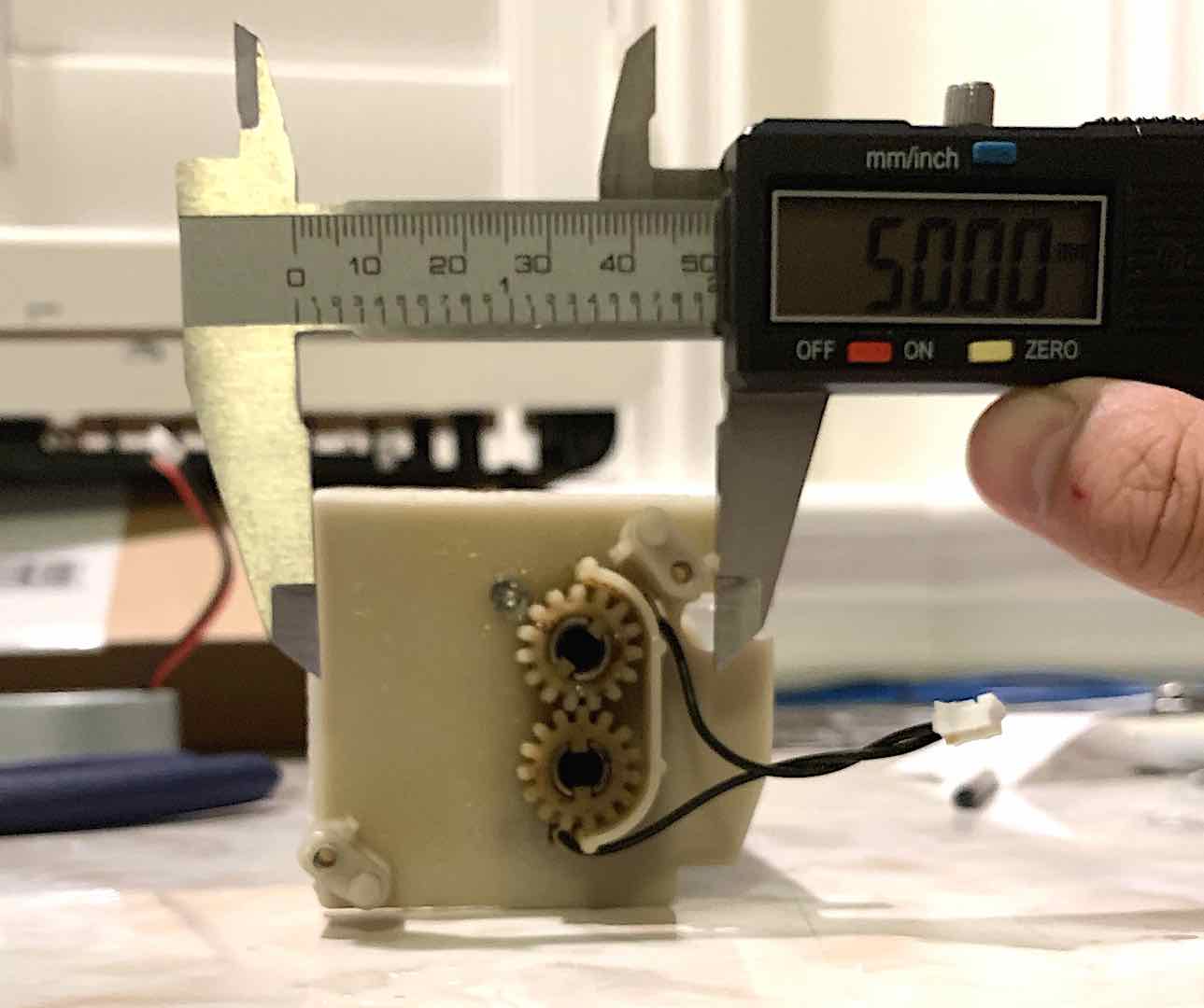
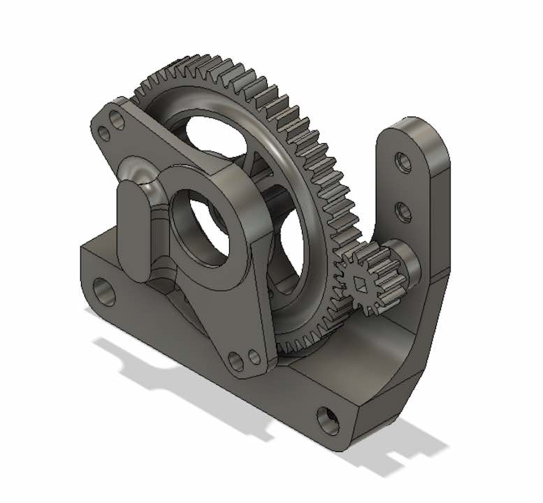
I made an early decision to use a rail system to mount everything because I had some 1/4″ shafts lying around.
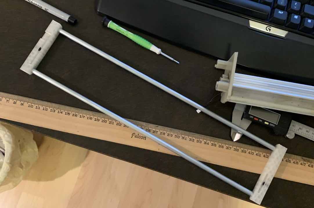
Surprisingly, even though I used PLA for all my parts, they were all far enough away from any heat source that I didn’t have to use a more heat resistant filament.
Magnetic Encoder
In order to complete a closed loop system, I needed some way of getting feedback for the motor position. I had a bunch of magnets and a two Hall effect sensors left, so I decided to try my hand at making a magnetic quadrature encoder. The concept is pretty simple. Just have two sensors whose square wave outputs (or sine wave if you want to do some fancy interpolation) are offset by 90°. To do this I fit a ring of magnets around the bigger gear with alternating polarities to ensure a clean, perfectly spaced square wave at the output. To create the 90° offset, I made spaces to glue two Hall effect sensors in such a way so that when one sensor was completely in the middle of a magnet, the other was in between two others.
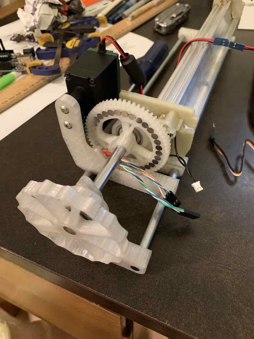
Although the resolution of the encoder would end up pretty low, it was very reliable, easy to assemble, and precise enough for the task at hand.
Closed Loop Control
In order to instruct the motor to go to a certain position as quickly as possible, I decided to take a page out of what I learned in Micromouse and implement a PI loop. Considering the pretty ideal operating conditions where stopping the motor would completely stop the rollers, I didn’t implement the integral completely accurately and just reset the integral when the error became 0. For tiny errors though, the integral component proved useful. Since the system was not very complex, I ended up tuning the PI loop by hand.
Making the Electronics
With motor control done and knowledge of heater control from v1, I threw all the electronics into KiCad. I picked the Atmega328P-AU as the microcontroller because it had all the features I needed while being easy to program. Funnily enough, I actually ended up using almost all of its pins.
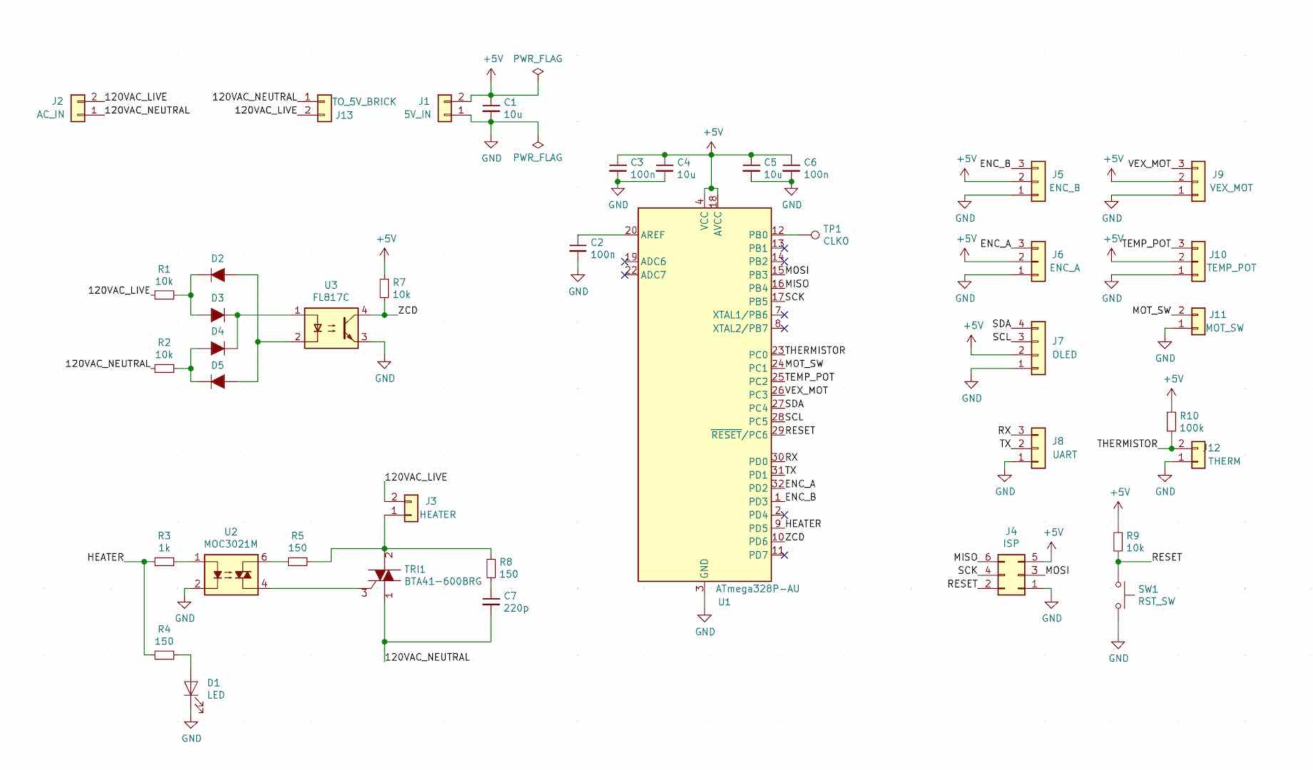
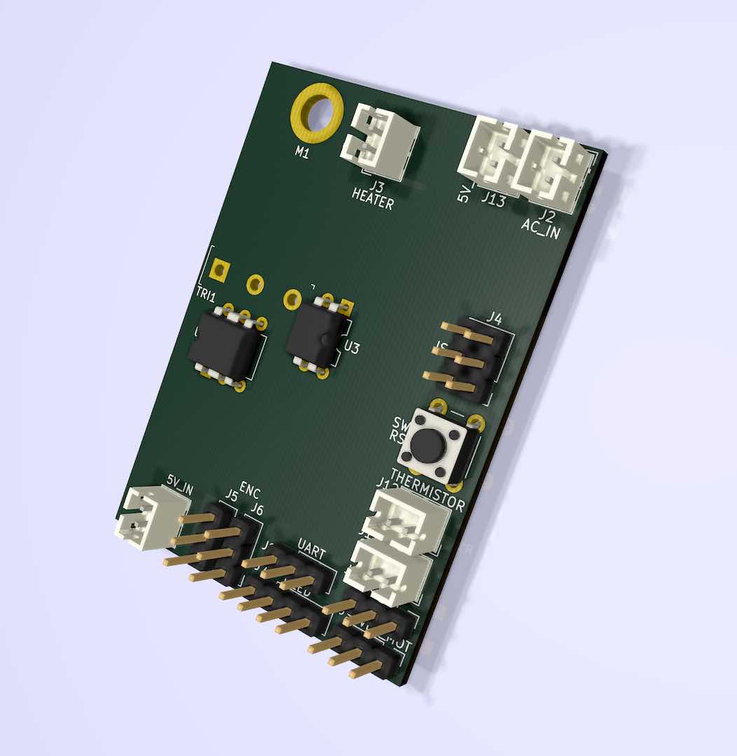
Most of the electronics are pretty much the same as v1, but in a nicer package.
Making the PCB
Using the v1 hardware to control the temperature and a separate Arduino for the motor, I was able to get a functioning prototype of the final laminator. It was also the perfect opportunity to test the whole process.
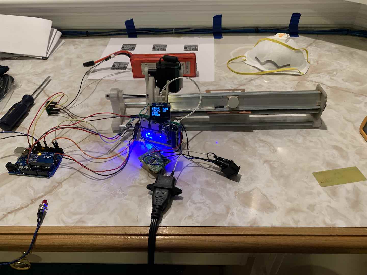
To my pleasant surprise, the transfer worked perfectly on the first go.
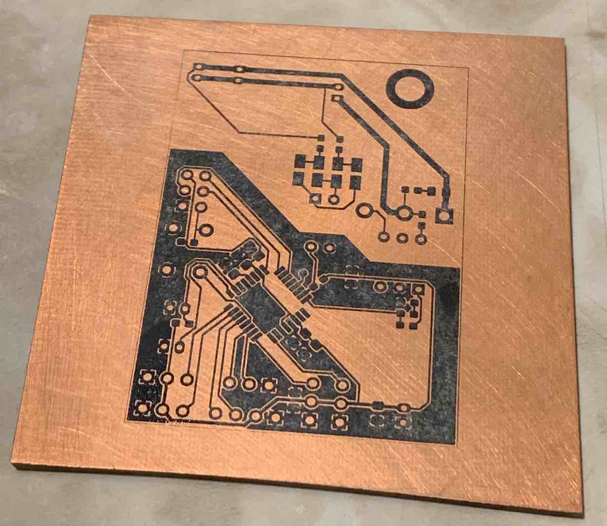
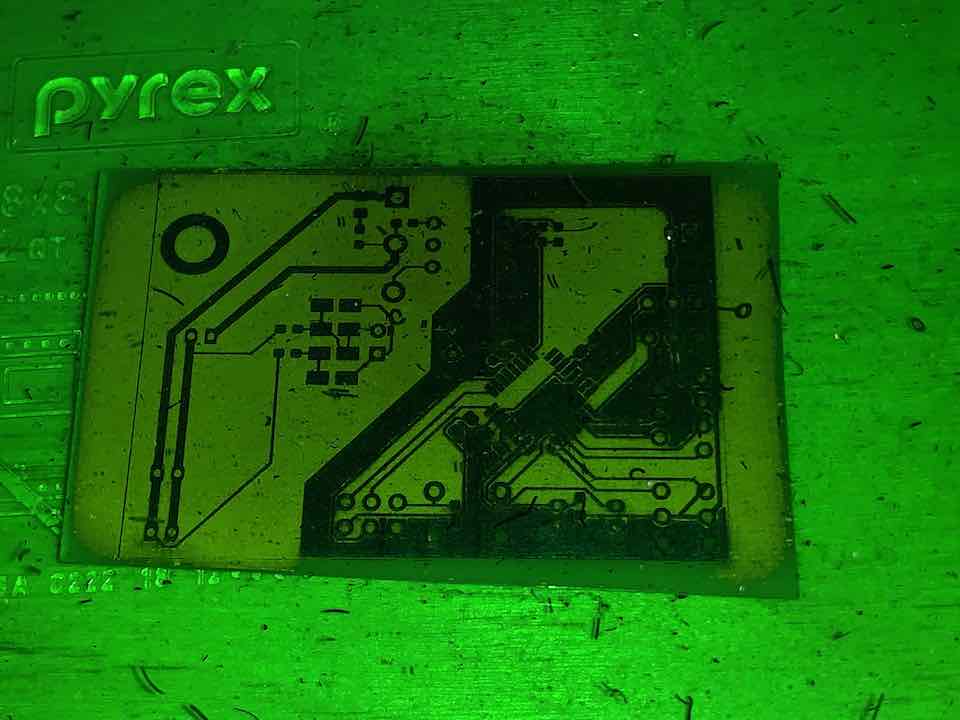
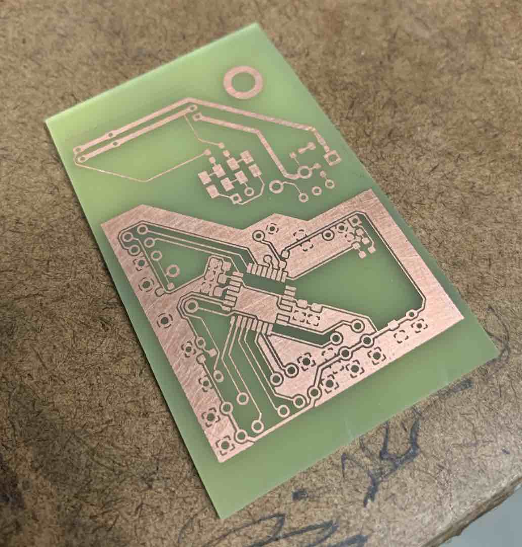
The rest of the assembly process for the electronics was relatively straightforward.
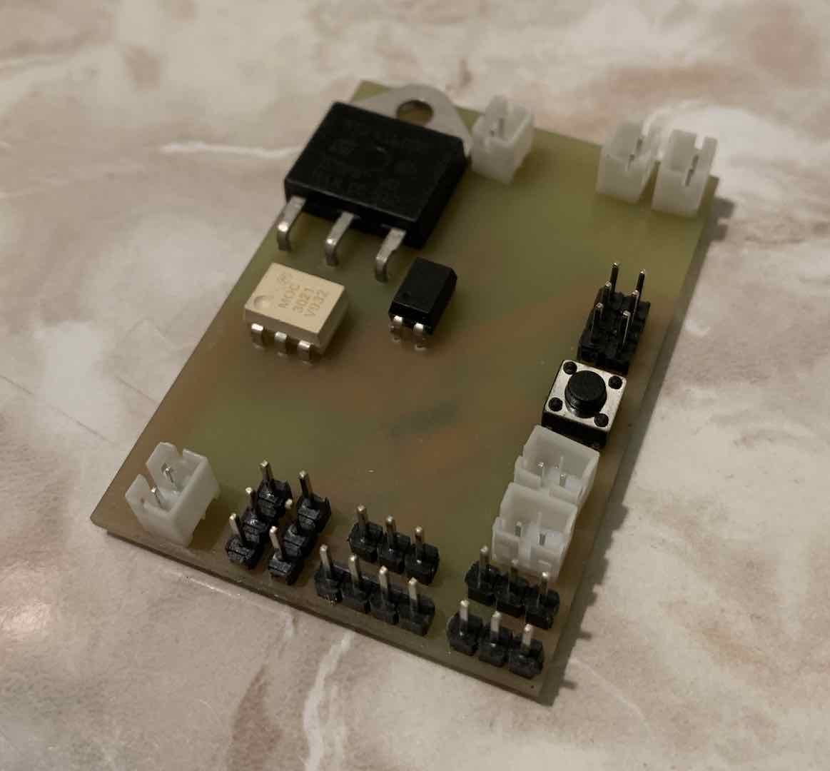
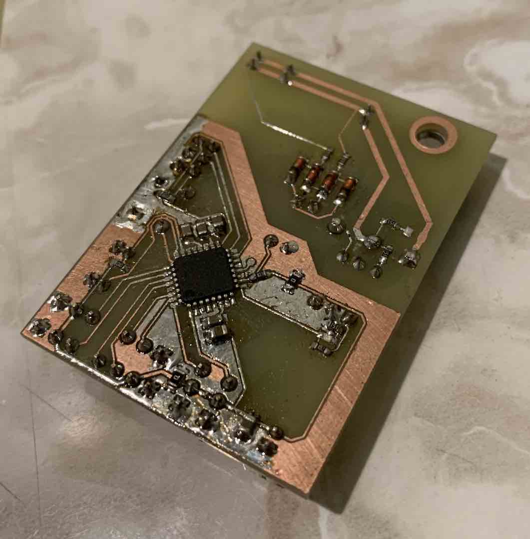
Finishing Up the Hardware
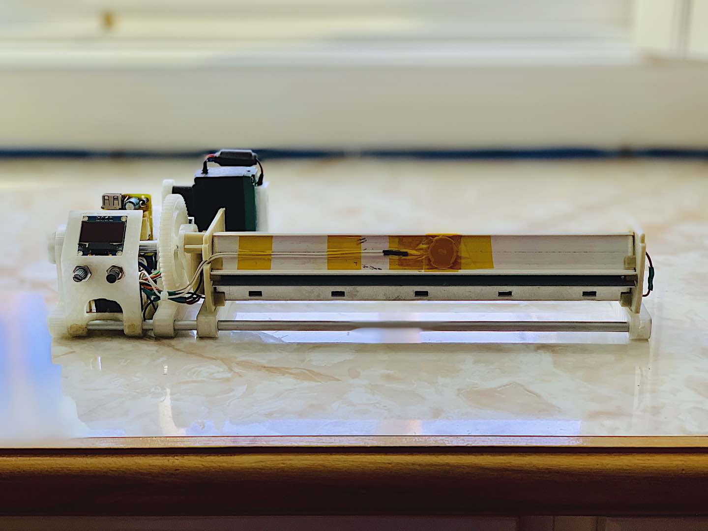
With the electronics done and the motor control ready, it was time to put everything together into one compact package.
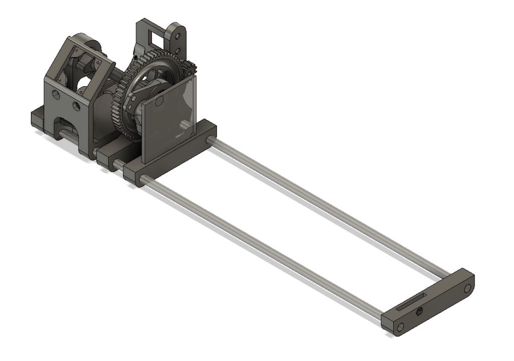
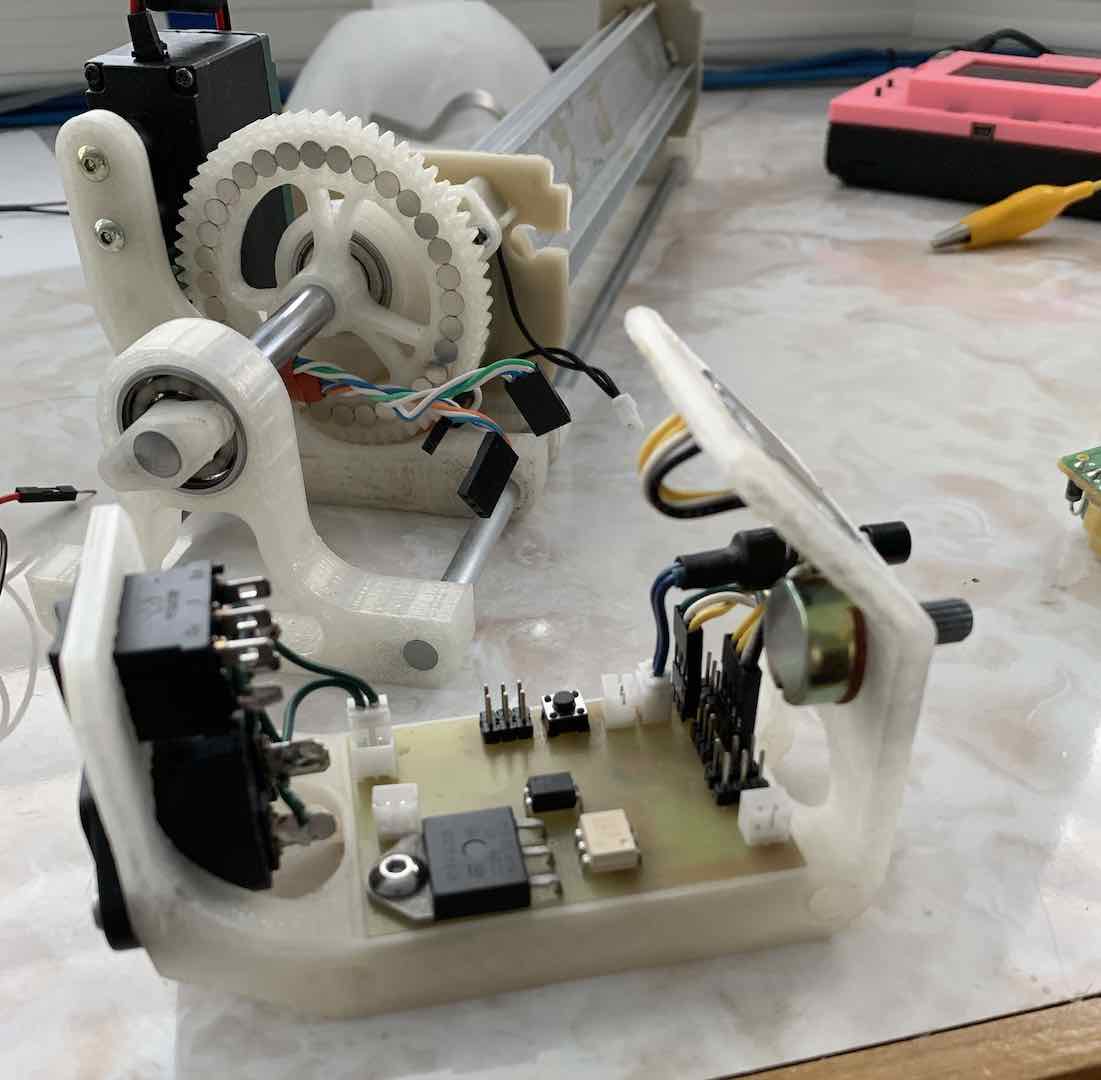
The main safety issue is still some exposed high voltage lines, but for the most part they’re tucked away. For maximum safety, in the future I can make a shroud for the electronics and ground any exposed metal.
Completing the Code
To finish everything up, all I needed to do was combine my motor control code with my temperature control code and add a user interface. The first little thing I had to solve was voltage drops caused by the high current draw of the motor and insufficient power supply. Current spikes occurred whenever the motor experienced a sudden change in velocity. I ended up solving it by limiting the rate of change of the motor velocity.
The rest of the code was pretty straightforward. Part of it was getting pin change interrupts to work. Most of it was little user interface tweaks to make everything easy to use. My code can be found here.
Tuning the PID Loop
The last thing to do was tune the PID loop for the heater. One thing I heard about and always wanted to try was using a computer to build a model of a system and then solving for the PID constants. I found out that I could use MATLAB and Simulink to do just this.
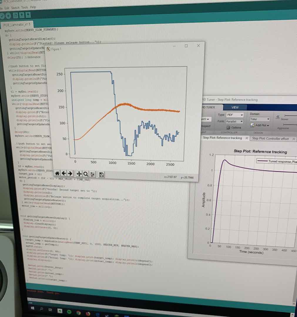
The gist of system identification is to collect a bunch of input and output data and throw it into PID Tuner to identify the system and then specify some parameters for the PID loop to get a desired response time and overshoot. After that, throw the constants into Simulink to see how the model behaves. One thing to keep in mind is that there is a maximum value for the input. You can’t turn the heater higher than a 100%.
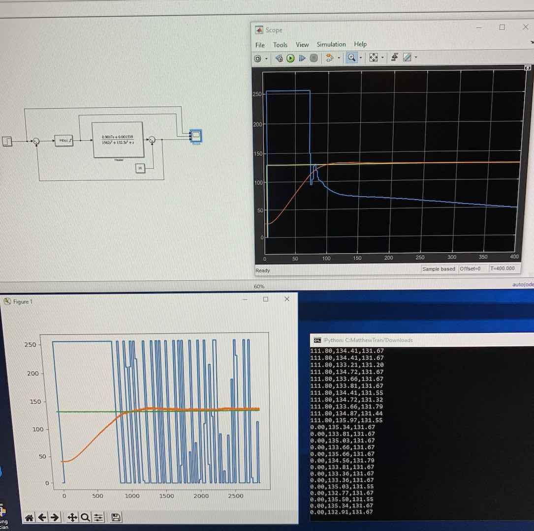
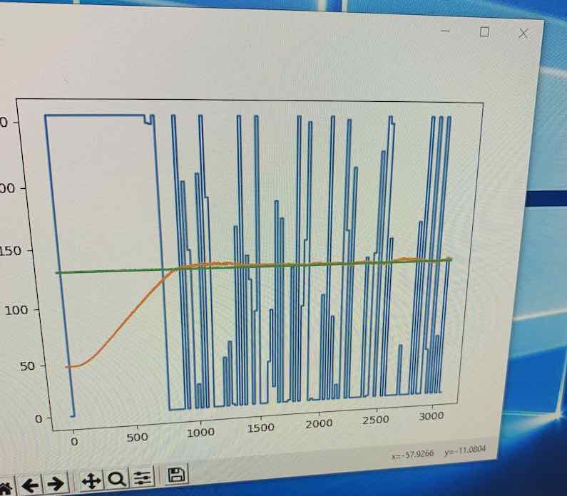
I’m not completely sure why, but the values the PID loop puts out in real life tend to swing between the minimum and maximum. Still, the temperature graph matched the model pretty well, so it all works out. Low overshoot and fast response time, exactly what I wanted.


Comments