
stbridge
Still on my quest of learning about non-shady ARM debuggers, I learned about the STLINK-V3MODS. It’s even got I2c, SPI, CAN, and GPIO interfaces all for $9 so I was hooked. After spending more hours than I’d like to admit getting the code to compile, I had a basic example working in C++. After spending even more hours than I’d like to admit getting a Python extension to compile, I also had a basic example working in Python. I even made my first open source contribution (yay!) in the form of bug fixes to a project that converted the bridge API library to use libusb. This conversion was necessary to make stbridge cross-platform compatible. Anyway, I’m a huge fan of self-documenting code so there isn’t much more to say.
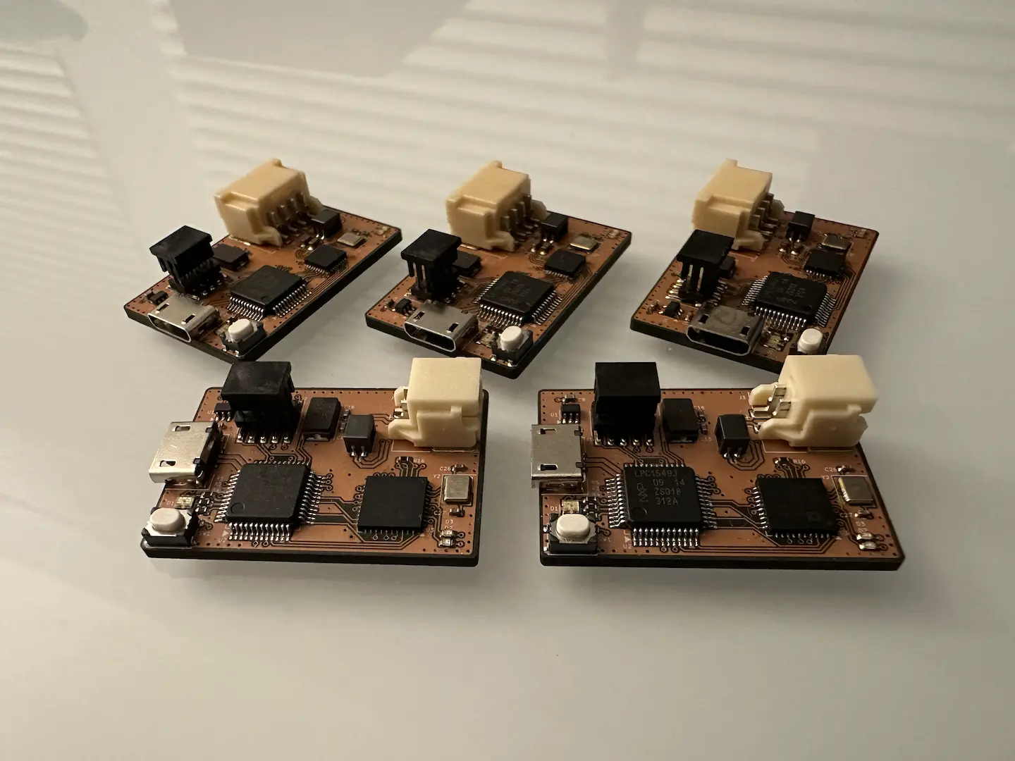
As far as a PCB breakout is concerned, I designed a KiCad footprint which is in my extraparts library. I’ve designed two breakouts, one of which I call NOGLINK but that one’s a little more specialized. There’s this person on Hackaday who also made a breakout but since OSH Park charges by area I had to design my own much smaller version. If people want the files for it I can throw it up somewhere.
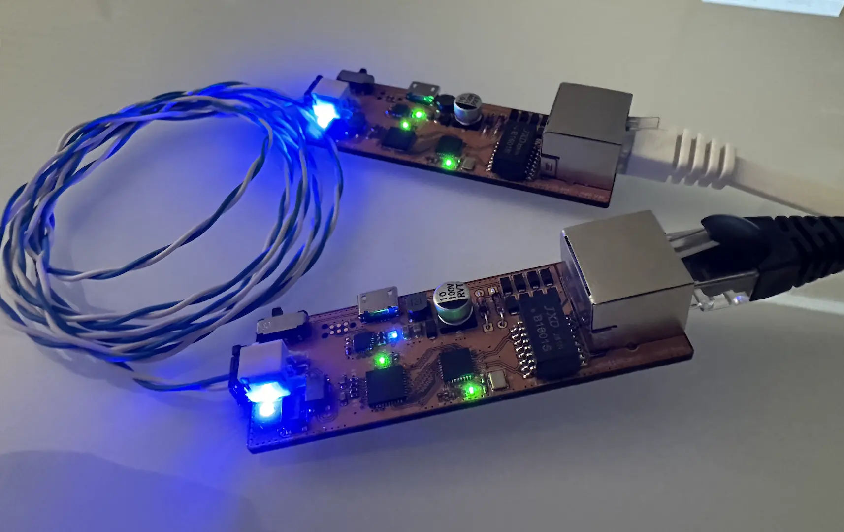
After doing some probing, I confirmed what the person on Hackaday said about pin 22 providing 5v. It appears that the 5v passed through a STMPS2151 and the main processor turns it on after some time. As such, it can source maybe 500mA. However, it’s important to note that this can literally change at any time since the pin is technically reserved.

Comments