
lpc1768_poe
miscboards/nxp/lpc1768_poe
kicadboards/breakouts/lpc1768_poe
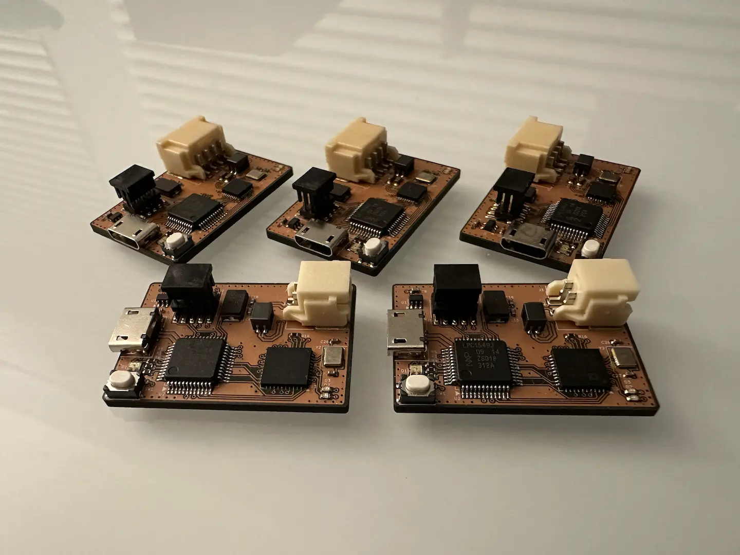
Currently in between projects, I decided to do a quick simple board. What resulted was not a quick simple board. It took two weeks to design on and off outside of work. I stupidly broke one in the process of testing, after which I grieved for several hours. The other two ended up working great, so I’m satisfied.
electrical
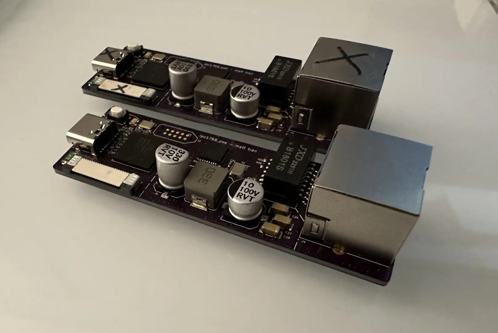
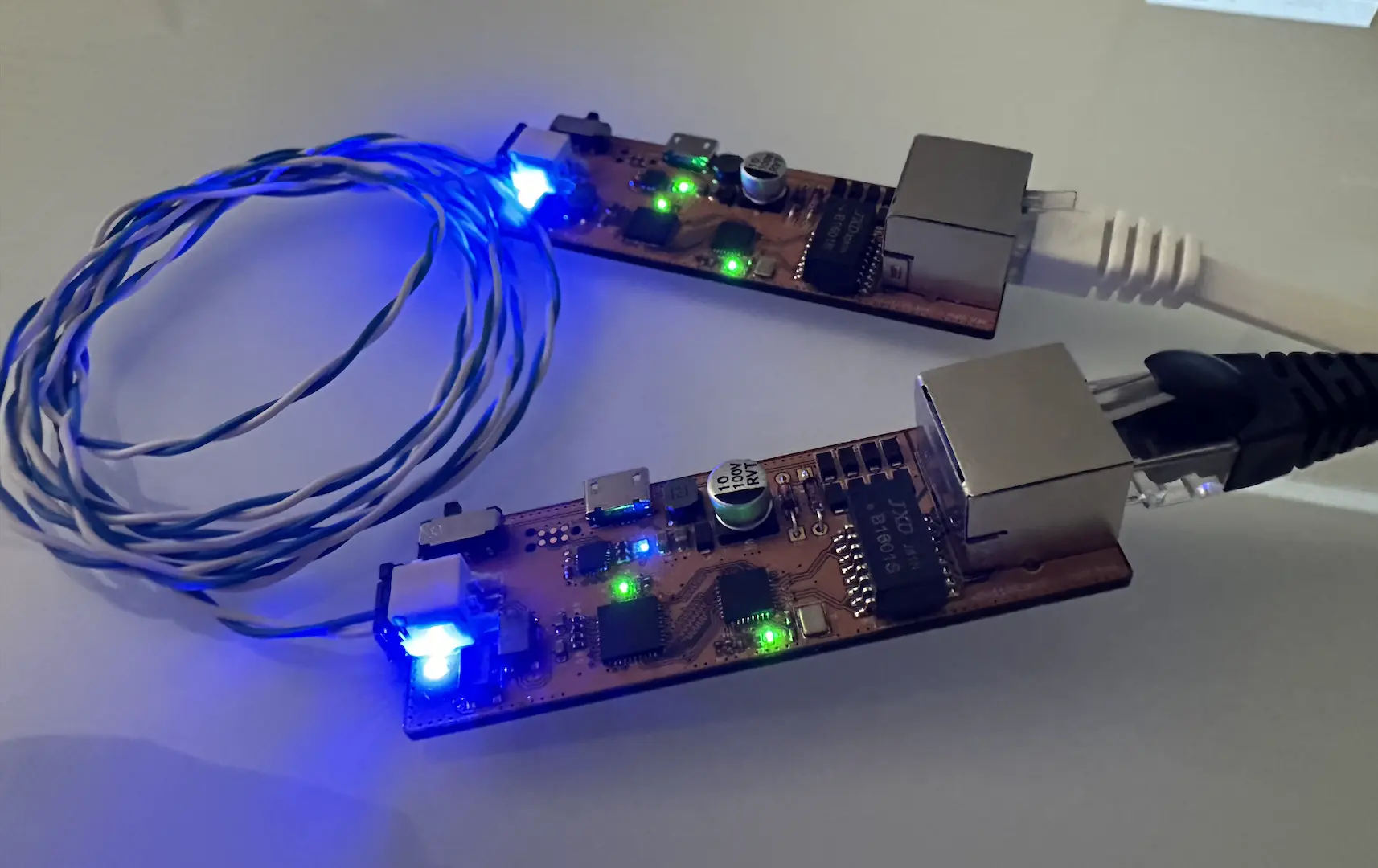
This was definitely one of the more difficult designs I’ve done in a while. Not so much in the circuit design complexity, but in the making sure I wasn’t doing anything wrong kind of way. To start, I wanted to do PoE. The concept is simple with the power traveling on the common mode of the twisted pairs, but the negotiation is where it gets complex. As a <15W PD, to get power from a PSE one must initially present a 25kΩ load, then a classification load at a slightly higher voltage. For >15W, one can do a second classification step or use LLDP. Then the PSE will supply the roughly 48V power. To keep the power on, one must present a minimum load for some minimum time for each period. To minimize size and complexity, I found the Si3402-C which would handle both the PoE negotiation and has an integrated switching regulator. Following the design guide, I was able to get a circuit together. Instead of an isolated supply, I kept it simple and used the buck regulator mode which interestingly shifts the ground up instead of the 48V down. If I keep everything in a plastic box, it should be standards compliant. For the minimum load check, I didn’t want to rely on firmware so just added a couple LEDs.
Next I wanted to use one of the cheap RTL8201F PHYs I got off LCSC. The datasheet lacked example circuits but I found other people’s designs to reference. The design was very much like the other PHYs I’ve used. The only thing I wasn’t sure about was whether external 100Ω termination was necessary. Some designs had them, some designs didn’t. I ended up adding them and it seems to work. What’s cool is that 100BASE-TX doesn’t have polarity and the PHY supports auto MDI-X which eased layout.
Doing the Ethernet magnetics was another whole thing. In all honesty, none of it really matters. I used 100nF for the PHY-side common-mode termination. For the Bob Smith termination I used what I saw in another PoE design. Importantly the center tap of each pair needs to be AC-coupled instead of being directly connected through the 75Ω termination.
The layout was rather fun and I put a lot of effort into trying to do it right. In all honesty, none of it matters that much but it’s good practice for when it eventually does matter. Even though it isn’t really an isolated design, I had a solid keepout between the power, microcontroller, and RJ45 regions. The board was slightly larger so I could fit the giant inductor and caps all on the top. The RMII traces were length matched. The USB and Ethernet differential pairs were also skew and length matched. I should’ve put the 100Ω termination closer to the PHY, but instead had it closer to the magnetics. One of the features I missed from Altium was its incredible trace impedance calculator, especially its coplanar differential option which doesn’t seem to exist anywhere else. I ended up using the standard coupled microstrip line option from KiCad. I probably should’ve increased the keepout between the diff pairs and the surrounding copper pour to make that option more accurate.
Initial testing was great as the PoE worked perfectly and the USB was working. I spent some time trying to debug why the 100BASE-TX wasn’t showing a link up. Probing the signal, it seemed to be stuck in 100BASE-FX mode which was weird as I set the strapping resistors for UTP. Thankfully, during firmware bringup a software reset over MDIO got everything working. The only mistake in my design ended up being the pin I used for the user button didn’t have an internal pullup, I had to add one.
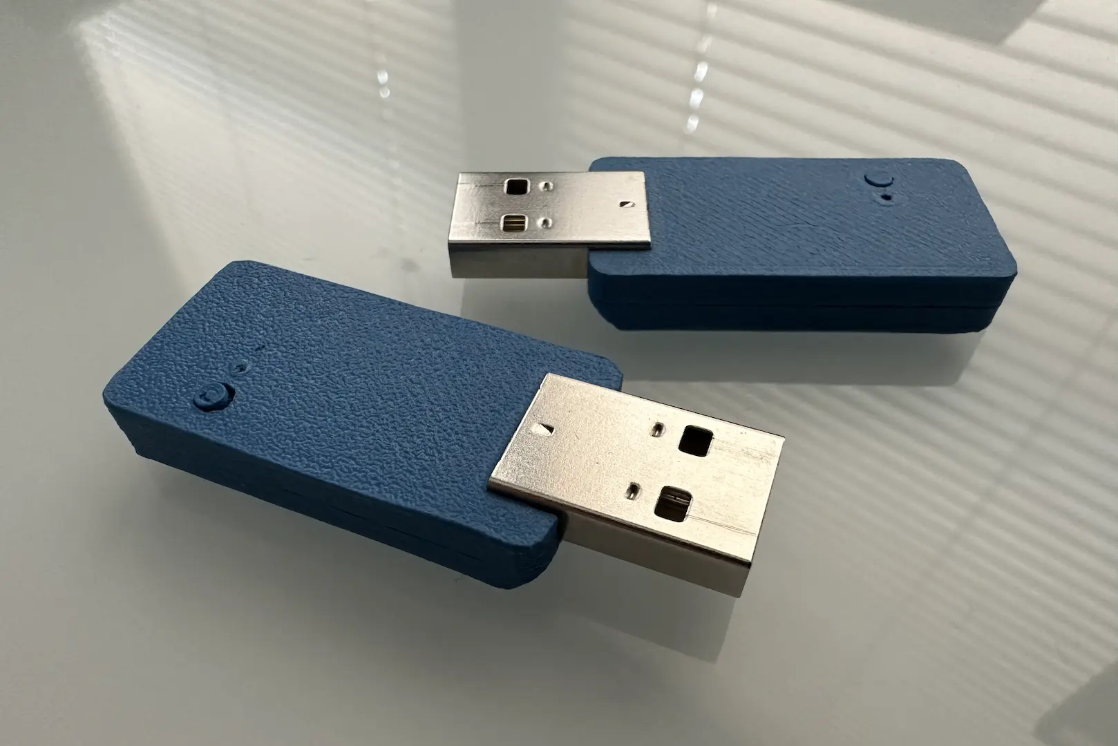
During testing, I plugged in PoE and USB C to my Macbook Pro to see what would happen, which ended up being nothing. Then I tried it on my desktop and the board popped. I learned a sad lesson that day, there’s a reason power supplies should be OR’d together. I assume my desktop lacked adequate protection and caused the PoE buck to output too much current which made it fail, dumping the full voltage into the rest of my circuit. Thankfully, my desktop didn’t break.
firmware
The firmware development was quite straightforward, no difficult to track down bugs. I started with only the compiler and LPC1768 SDK and got C/C++ support going. It was pretty fun writing the startup code for the Cortex M3 core. I added a basic ROM vector table with hardcoded LPC checksum by fixing the reset handler location. Then I moved the entire vector table into RAM. Then I added in FreeRTOS and TinyUSB, both having great support for the LPC1768. I initially had a hard fault since I didn’t copy over the first two entries of the vector table from ROM into RAM. Other than that, smooth sailing.
From there, it was time to write my first Ethernet driver. Well, I did the MDIO part first to check the PHY was working. At a low level, Ethernet is based on sending and receiving variable length packets. The CRC check is generally done in hardware so we only have to worry about what bytes to send. Since the interface is so fast, most implementations use DMA. In the case of the LPC1768, we specify a ring buffer of DMA descriptors that get processed as needed by the Ethernet peripheral. I ended up allocating my RAM buffers in the secondary RAM region as this was a good application for it. Once I had a basic send/receive API working, I could continue.
The hardest decision to make was choosing the TCP/IP stack. This builds on top of the raw Ethernet packets to give you all the features typically associated with networking. Traditionally lwIP is used, but from what I read it’s getting old and the documentation is poor. I ended up using the FreeRTOS+TCP stack since it had good documentation and integration with FreeRTOS. I started with the MDIO driver to control the PHY. Basically we just need a thread to monitor the link status and update the stack and MAC if anything changes. Importantly, we need to call FreeRTOS_NetworkDown() on a link up to restart the DHCP process. FreeRTOS does actually have an API for MDIO, but it lacks RTL8201F support since it lacks the expected 0x1F register, so I didn’t use it.
Once MDIO was working, integrating the Ethernet driver was next. For maximum speed, BufferAllocation_1.c and zero-copy driver are recommended. While those are supposed to be advanced features, implementing them together was actually easier than if I had done it the normal way first. It’s a good thing I ignored the warnings. For BufferAllocation_1.c, there is a fixed pool of network buffers pointing to statically allocated packet buffers, which I allocated using the entire secondary 32kB RAM region. For zero-copy TX, we simply need to set the next free DMA descriptor to the network buffer’s packet buffer and free the last network buffer if needed. This uses a bit more RAM but is simpler. For zero-copy RX, upon RX interrupt we awaken a thread that simply allocates another network buffer and then pushes the filled one to the stack. BufferAllocation_1.c and zero-copy work well together because we know the network buffer’s packet buffer never changes which greatly simplifies the code. The speed does come at cost of more RAM, but it’s fine since I have plenty.
Once I had the TCP/IP stack running with mDNS and DHCP, I needed a basic app to demonstrate functionality. What better way than an HTTP server. lwIP has one but I couldn’t use that. FreeRTOS’s HTTP server still remains an example. I ended up settling on Mongoose which advertised FreeRTOS+TCP support. It does work, but only using the legacy API which meant no IPv6. It doesn’t appear to be multithreaded by default, so couldn’t support more than one TCP connection at a time. That’s how I learned that browsers typically don’t close their sockets when a tab is closed.
Overall, this was a nice foray into the world of embedded networking. I still have much to learn, but this is an excellent start. There are still plenty of configuration options that I barely understand.

Comments