
Playing with 10BASE-T1S and 10BASE-T1L
miscboards/nxp/lpc1549_oaspi
kicadboards/breakouts/ncn26010_oaspi
kicadboards/breakouts/adin1110_oaspi
Since microcontrollers with built-in MACs tend to be more expensive, external MAC-PHY chips can be used instead and talked to over SPI. Open Alliance SPI standardizes the communication protocol so that roughly the same driver can be used for any MAC-PHY. With sufficient CPU and SPI bandwidth, one can achieve the full 10Mbps of either 10BASE-T1S or 10BASE-T1L.
hardware
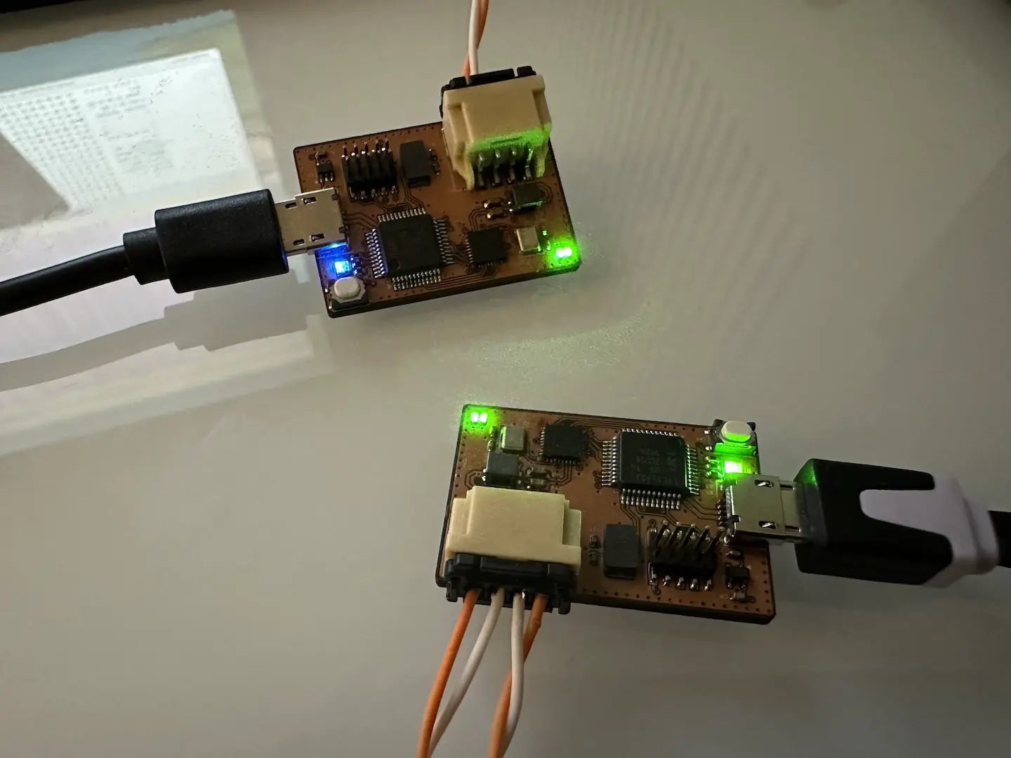
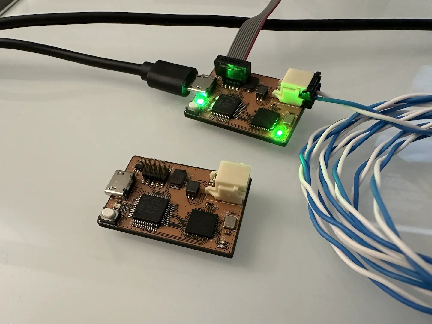
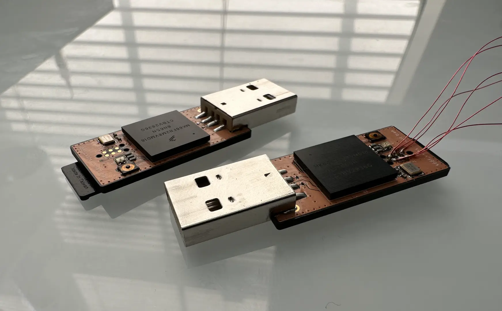
I did a board design for each of 10BASE-T1S and 10BASE-T1L, using the NCN26010 and ADIN1110 MAC-PHYs respectively. The circuits for them are quite simple, I mainly just followed the datasheet and evaluation boards. For 10BASE-T1S, it’s important to note that the end and drop nodes have different termination. The drop nodes don’t need termination, but adding a little generally helps noise immunity. Since I had samples, I chose the LPC1549 as the microcontroller. The connection from the MAC-PHY to the microcontroller is like any SPI device (SDO, SDI, SCK, CS) with an added interrupt pin.
For the layout, there isn’t much to say. I kept it pretty small and on two layers and was able to reuse much of the layout between boards since they were so similar. The switch matrix of the LPC1549 helped ease the layout since I could remap the SPI pins anywhere.
firmware
Starting out, I got the LPC1549 SDK running similar to how I did for lpc1768_poe. I ran into some issues where flashing once would end up with this one specific sector being empty. Flashing twice fixed it. Correctly setting the CRP helped significantly. Interestingly, the LPC1768 has the same CRP but I had no issues with it. This might be because the LPC1549 has a substantial bootloader in its boot ROM. Overall, the SDK was quite nice to use. I ran into some issues with a SPI DMA driver, but I got it working eventually. TinyUSB and FreeRTOS setup was smooth sailing as always to set up since it’s already supported.
For the Open Alliance SPI (OASPI) driver, I started by implementing control transfers which is how we interact with registers. For reliability, control transfers have a parity bit and send/receive the inverse of the data payload. For simplicity, I just retried the transfer until no errors were detected. The configuration for the NCN26010 and ADIN1110 are quite different with regards to the MAC filtering and PHY registers, but it’s overall quite similar. Next, I implemented data transfers. While it may not be the most portable, using bitfields was nice to parse out the packet fields. Data transfers use a parity bit to protect the header like with control transfers. To protect the data itself, the normal FCS of Ethernet frames is used, preferably for both TX and RX. I added a helper for that.
For connecting to an Ethernet stack, the exact implementation can vary. I wanted to make a USB converter so used the TinyUSB API which boils down to a function to send a packet and one to receive one. I started with a high priority thread that busy looped looking for and assembling received packets. Then I added the interrupt pin so the thread could sleep until RX data was available. After that, I added the ability to send packets which was a similar process to receiving packets and was sent on the same bidirectional data transfers. The thread would now only sleep if no RX data was available, no TX buffer space was available, and no TX packets are queued. The way OASPI defines interrupt triggers helps make sure the driver only performs data transfers when needed. In all of this, I also made sure to check for errors and just drop packets if I got any.
In terms of performance, the driver works pretty well. Measuring on an oscilloscope, the effective bandwidth is around 12Mbps if packets are aligned to chunk boundaries and roughly half that if not. About half the time is spent sleeping waiting for SPI to finish. Another quarter is the CPU processing and checking the packet data. The last quarter is FreeRTOS task switching overhead which I could potentially reduce by setting up longer SPI transfers at the cost of latency and memory. For reference, this is a 72MHz Cortex-M3 with some flash latency.
In the future, it would be good to buffer the packets going to and coming from TinyUSB. I’m definitely losing some packets if the OS doesn’t read fast enough. It would be fun to play with cut-through mode for OASPI, squeezing a TCP/IP stack on, PoDL for 10BASE-T1S, topology discovery, and IEEE 1588 hardware timestamping. For now, this was a successful exploration.
update 1-19-25
Since the initial completion of this project, I’ve continued work on it and it has become something I’m quite proud of. Using task notifcations instead of binary semaphores improves speed, although I haven’t measured by exactly how much. I did a massive refactor of the code to decouple the TinyUSB application from the Ethernet layer, creating portable Eth and OASPI classes in the process. To minimize copying, packets are now allocated and deallocated from a fixed size pool of maximum length packets. Doing this also made buffering packets between TinyUSB and the Ethernet layer easy. Since WSL doesn’t come with RNDIS/ECM drivers, I also switched to NCM for true driverless use everywhere. Even more, I modified the HID interface to allow arbitrary OASPI register options, which even allows a webpage to access it using WebHID. As a proof of concept, I also implemented my Eth class in macOS using libpcap.
Currently I’m limited to about 6Mbps due to my use of USB FS. If a MAC-PHY with topology discovery ever becomes publicly available, I’ll definitely build a new board with it and USB HS. If I get paid to do it though, it might have to be closed-source 😧.
update 5-21-25
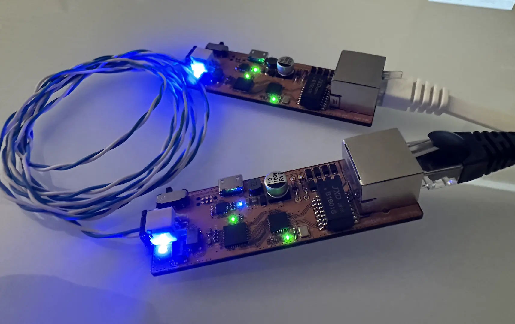
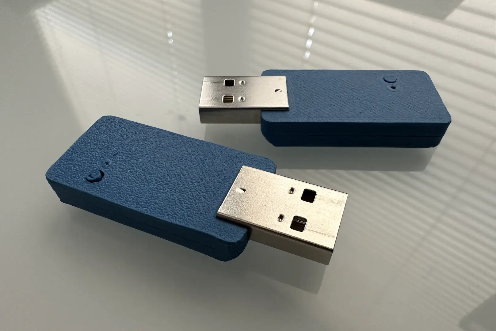
Well looks like $DAYJOB needed an in-house USB to 10BASE-T1S dongle. The full design will never be open-source, but I’ll discuss high level details here. For the hardware, I switched to a microcontroller from the STM32U5 family since it has USB HS with a built-in PHY and USB PD. The not-yet-publicly-available MAC-PHY importantly supports topology discovery. To support powering 48V/5A devices, I added a beefy PoDL injector circuit and associated HSD. From a raw parts perspective, that board is one of my most expensive.
On the firmware side, the first change was supporting multiple microcontrollers, board configurations, and applications. I then expanded the HID RPC significantly to support the HSD and topology discovery controls. I also fixed the macOS BIOCPROMISC issue which was a capabilities advertisement issue. As you might guess, the intention of the Eth class was to also implement it on Windows, macOS, and Linux so I could build applications that run cross-platform. Without revealing too much, I can say that the custom protocol library I’m working on at $DAYJOB works seamlessly across embedded and desktop OSes.
In terms of performance, I can hit 9.5Mbps in CSMA/CD mode which is about the maximum one can expect for 10BASE-T1S. Topology discovery also works well after tweaking the PoDL circuit inductance a bit to fix ringing issues with some MAC-PHYs (Onsemi cough-cough). As my first Altium/mouse board in almost 4 years, I’m quite proud of it. If I ever leave $DAYJOB I might talk more about it, but this is where the open-source side of the story ends for now.

Comments