
Robot Arm 2017
Written 9-29-19
Coming into the SciOly 2017 season, it was clear that the rules had completely changed from the previous year. Last year’s task was easy enough that pretty much everyone at Nationals got a max score. Just looking at the new task, I could tell that perfect scores would be incredibly hard to come by. This year there would be 5 stacks of 10 pennies each placed around an archery target, all initially heads up. To maximize our score, we had to flip all the pennies, spread them out so there’s no overlap, and then push them as close to the center of the target as possible.
v1
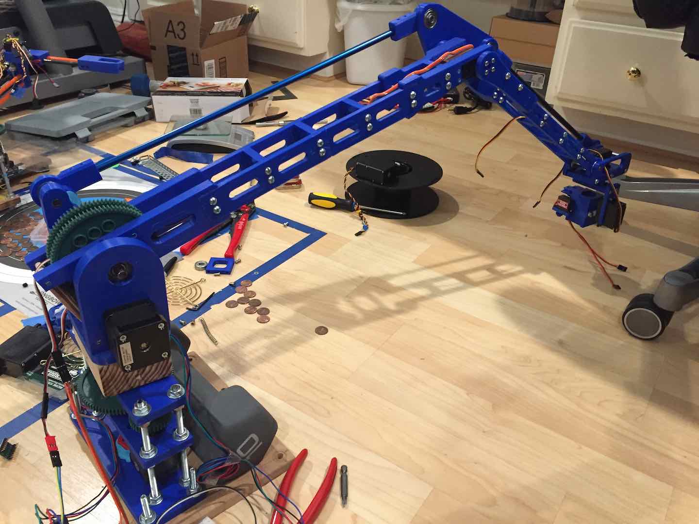
Since I initially wanted to focus on the end effector design, I started out by modifying my robot arm from last year. The new rules required a longer reach and smaller base, so I started by cutting down last year’s base and extending the arm by a bit. Since the base was so small, I couldn’t use the 10 lb. dumbbell from before. I ended up cutting several steel sheets to make a 10 lb. stack. My ears were ringing after using the angle grinder for so long but it worked out. Decent ear protection was quickly added to my toolbox.
End Effector
Next up was the end effector. My idea was to create a sort of cylinder that could be placed over a stack of pennies. Then I would pinch the bottom penny to hold the stack in place. From there I’d lift the whole stack above the ground, flip it over, and dump the contents onto the archery target. Then I’d go in and spread the pennies out so that they don’t overlap.
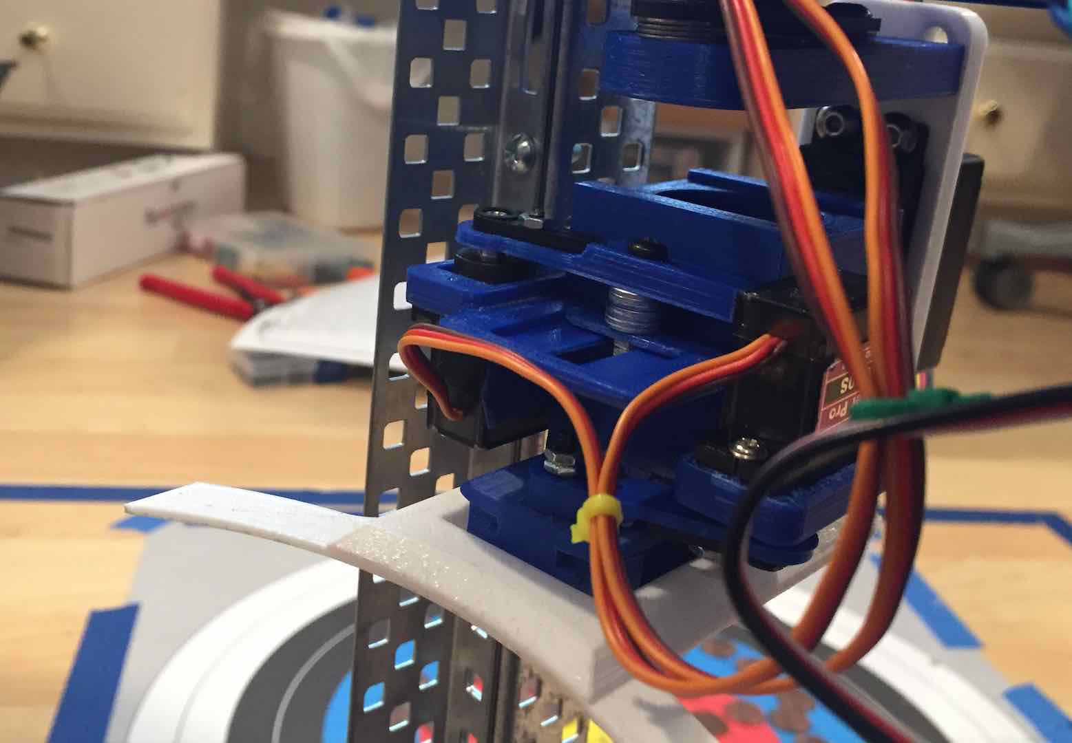
One interesting part of designing the end effector was making a linear actuator to get the servo to pinch parts. Because of the size restrictions, I designed the rail myself. Getting the tolerances good enough to balance friction and backlash took some trial and error. I attached it using superglue and later used acetone.
Parallel Mechanism
Next, I modified the arm to make the end effector parallel to the ground at all times. This would make it far easier to reliably pick up stacks of pennies. I’m still not completely sure what the exact name of the mechanism is, but I call it a parallel mechanism. I built one a couple years ago, but I never understood why it worked. Upon closer inspection and experimentation with my Vex parts, I realized how simple it was. Essentially build two linked parallelograms. The offsets for the linkages were chosen to ensure proper operation over the entire range of motion.
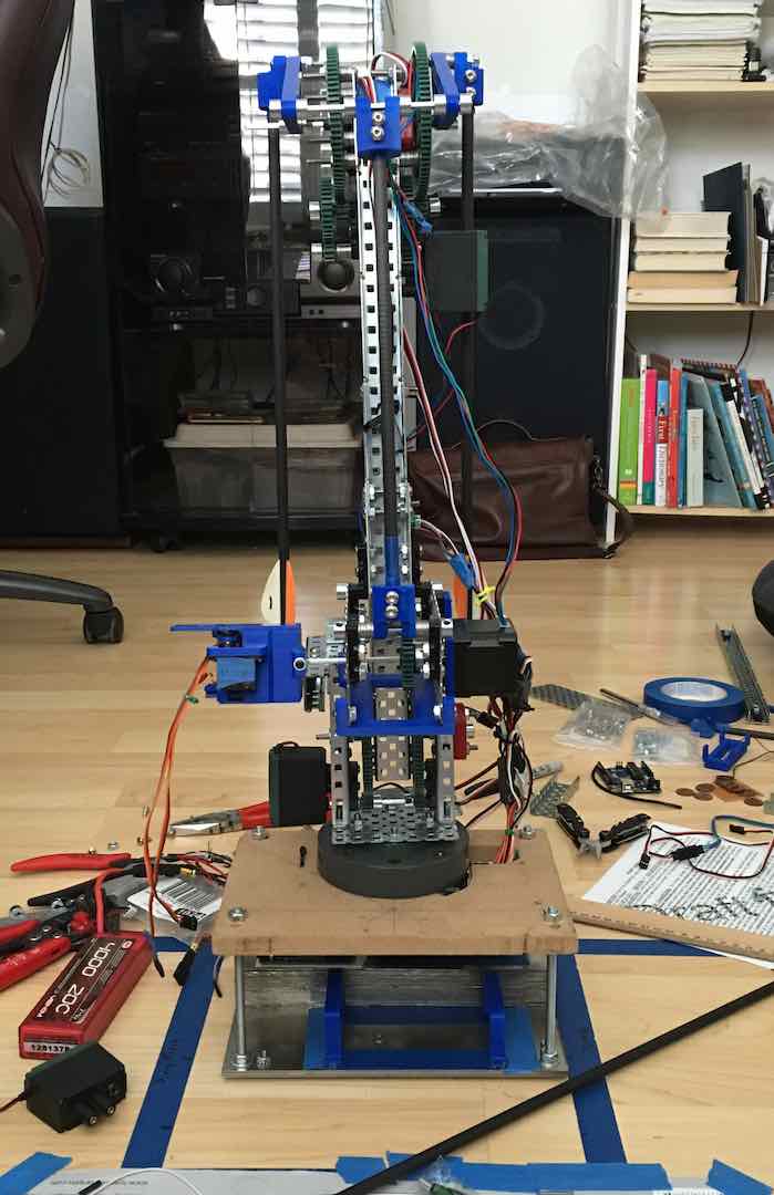
Testing the arm out, it was safe to say that it did not perform very well. It certainly could pick up every stack of pennies and flip them over. However, dealing with overlapping pennies and moving them around took too much time. It also felt more like a last minute hack than an actual solution to the problem. Still, the things I learned from this arm paved the way for v2.
v2
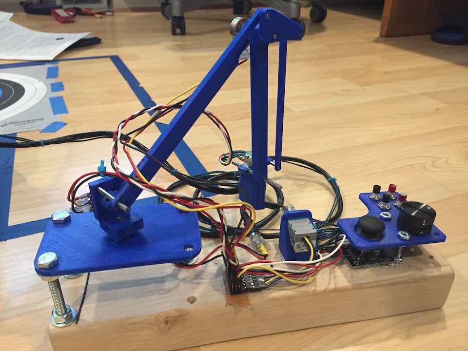
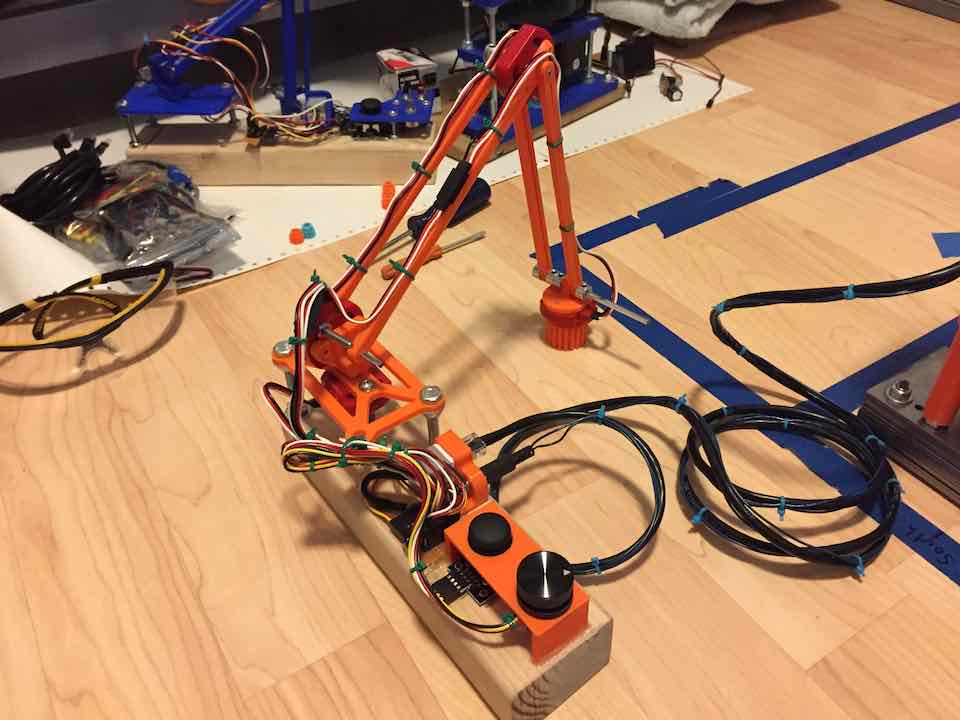
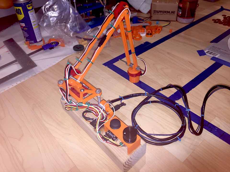
With v2, I decided to completely do away with the parallel mechanism design. The task didn’t really involve manipulating objects in 3D space, except for maybe moving pennies up and down. After some research, I decided to use a SCARA design, which works really well with 2D workspaces. It would also lessen the load on the motors since they didn’t really have to carry anything, just move things side to side.
End Effector
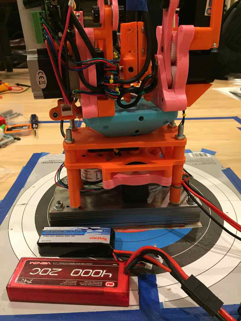
Before implementing the SCARA design, I needed to revamp the end effector design. The main issue was quickly spreading out the pennies without overlap. My head coach Mr. Wahl had the brilliant idea of having a single penny thick slot at the bottom of the tube that could let pennies out one at a time when dragged across a surface. The prototype worked absolutely perfectly, so I went with it. I was worried about the coefficient of friction at first, but a quick jolt gets all the pennies to slide out, so it works.
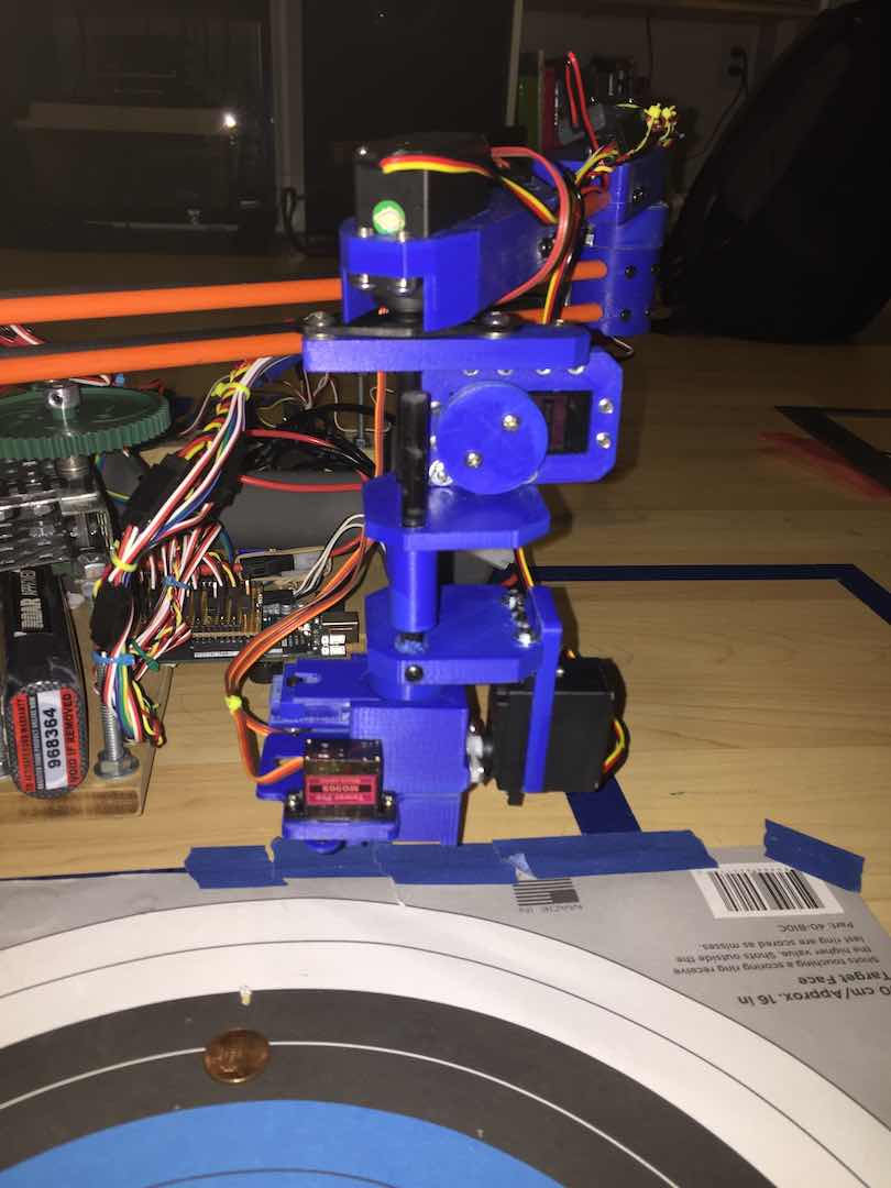
Here’s the finalized end effector. The slot at the bottom is two sided, so pennies would only exit in one axis. Two servos control flipping the entire container over and changing its rotation. Another servo on the container holds the penny stack in place so that it doesn’t fall back out when flipping. Yet another servo uses a string to lift and lower the container. As you can probably tell, I used quite a few servos, but my controller design made it all relatively intuitive.
SCARA
Next up was attaching the end effector to an arm. Since I didn’t yet have experience in making stiff 3D printed parts, I just used some fiberglass and carbon tubes. The “shoulder” joint was constructed with a Vex motor and potentiometer like last year. After some PID tuning, it worked rather well. Motor choice for the “elbow” joint, which was heavily limited by space, proved tricky but I found a workable servo. The issue was that servos typically aren’t tuned for high inertial loads, so there were oscillations.
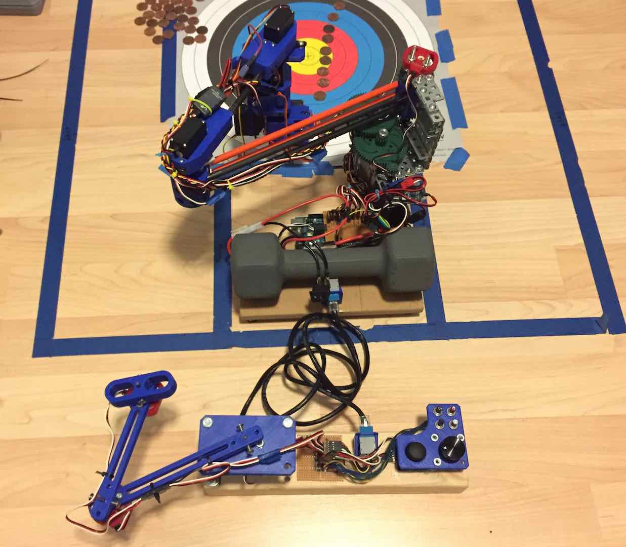
Score-wise this robot arm was a vast improvement from v1. I really liked trying out a completely new arm design. However, the biggest issue was getting enough reach out of the arm with my at the time amateur design skills. The arm really pushed the size limits of the rules, which is something I don’t like doing. Joint stiffness was also an issue as the arm tended to curve at medium extension. Overall, the arm worked well, but it didn’t feel reliable or clean enough to take to Nationals.
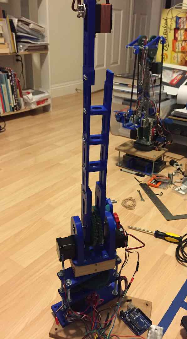
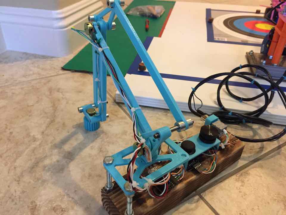
v3
Dissatisfied with v2, I started work on yet another arm. With more CAD experience behind my belt, I got to work designing an almost entirely 3D printed arm. I intended for this arm to be the culmination of everything I learned from v1 and v2, fixing everything from reliability to usability to aesthetics and more.
End Effector
Since I knew v2’s end effector was pretty reliable, I didn’t spend too much time redesigning the end effector. In fact, if I remember correctly, I literally took the v2 end effector and slapped it onto v3 when I was done and took that to tryouts. The only real change I made was gluing on an arc to aid in moving pennies around.
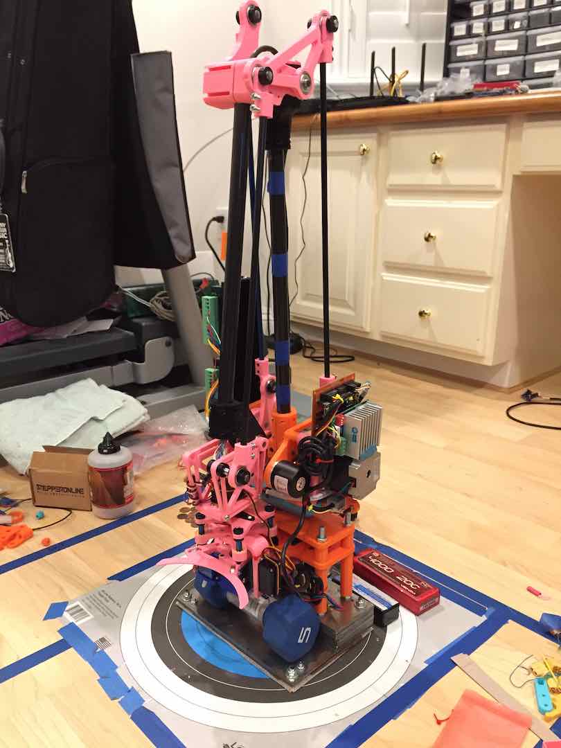
Parallel Mechanism (Again)
My main focus for this robot arm was improving accuracy and speed of the joints. I liked the SCARA design, but at the time lacked the mechanical know-how to implement it more effectively. Knowing exactly how the parallel mechanism worked by this point, I started off with motor choice and torque calculations. Since I needed the precision, I used some stepper motors I had lying around for the turret and shoulder joints. Due to still not having enough torque and some backlash issues, I added some rubber bands. The elbow joint was trickier because of the high inertial load like with v2, but after going through 3 or 4 servos I found one that worked.
The arm performed very admirably. Scores weren’t vastly improved from v2, but usability, flexibility, and reliability improved. Still, I was not satisfied with the rubber bands and the oscillations caused by the servo motor in the elbow joint. The end effector also had a bit of friction and was not the most pleasant to use. Overall, it performed very well, but there were so many little things I wanted to improve. What it did do was cement the design I would use for the final iteration.
v4
During winter break, I decided to completely redesign the arm. v3 performed well at tryouts but I knew it wasn’t good enough for Nationals. With a lot of experience under my belt, I listed out all of the problems in the previous arms and immediately got to work.
End Effector
Surprisingly, I actually ended up working on the end effector later in the year but it proved the most important thing to upgrade.
Knife Ramp
One issue that popped up while using v3 was that the servo used to hold the bottom of the penny stack broke after awhile. I was basically stalling the servo to provide a pinching force, which likely damaged the cheap motor controller. While I did upgrade to a name brand servo, I still wanted to ensure the problem would never show up again. Wanting to exercise my knife sharpening skills, I came up with the idea to make a steel ramp that would slide under the penny stack. It worked very well.
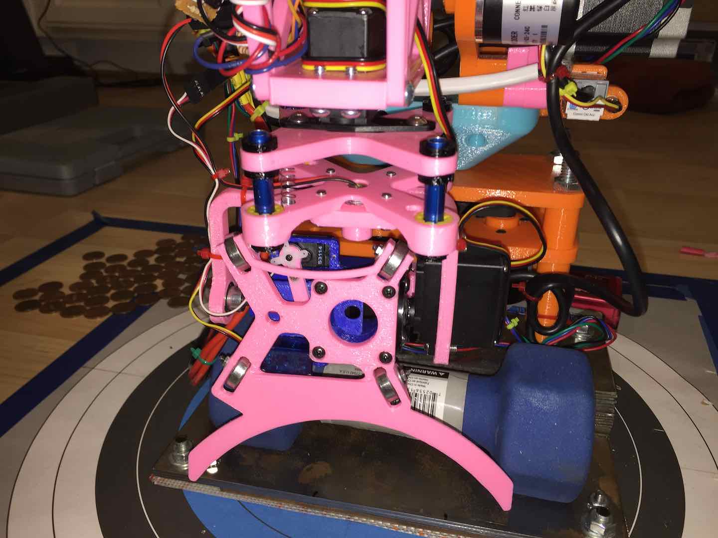
Omnidirectional Penny Slide
From a usability point of view, I didn’t like how the pennies could only slide out in two very specific directions. There was also a decent amount of friction that caused me to mess up sometimes. To fix this, I made the slot omnidirectional, letting pennies slide out in any direction. I did add a couple arcs to aid in pushing pennies around which restricted some motion, but overall there was a lot more wiggle room. Also, bearings vastly improved the smoothness of the sliding.
Stiffness Improvements
An issue that popped up during testing was that under too much pressure, the end effector mount would flex. One end of the end effector would lift up a bit, making picking up stacks difficult. To fix this, I added a shaft on the opposite end of the flipper servo to support the end effector on both sides. Making room for the shaft did take a bit of redesigning to ensure it didn’t interfere with other parts.
Suspension
During one of the invitationals, I learned that the arm was actually strong enough to lift the front of its base off the ground. Sometimes this also put the end effector out of alignment. To fix this, I added a weight at the front, negating any leverage the arm had with respect to the base. This worked, but created a new problem. The stepper motors in the joints would skip steps when pressed against the ground, which I did quite often. To ensure I wasn’t applying too much pressure and have a visual cue for that, I designed a suspension system.
Since I didn’t have much space or weight to work with, I experimented with 3D printed parts, pen springs, and aluminum shafts. I ran out of #4-40 set screws, so I designed some tight fitting clips made of PETG as clips to hold the aluminum shafts in place. Two springs provided just the right amount of feedback to work well. My favorite part was the igus-style PLA linear bearings I printed. It took some trial and error with the scaling, but eventually I got the bearings to slide smoothly.
Laser
This doesn’t really need it’s own subheading but yes I did add a laser to help with stack alignment 😁. To comply with SciOly safety rules, I used a Class II laser module.
Mechanical Design
Looking back at the design of the arm, I am still somewhat astounded that I didn’t use any assemblies in CAD to model it. The dimensions and relation of every part was done on paper and then modeled in Fusion 360. This does explain some of the bulkiness and slight design flaws of the arm though.
To improve accuracy and precision, I switched all of the high load joints to stepper motors and optical quadrature encoders. Since I didn’t want to run two stepper motors together like in v3, I switched to a single NEMA 23 motor for the shoulder. To lighten the arm and make room for the encoder, I moved the elbow motor to the base, using a similar parallelogram mechanism to transfer the force. Due to not having good places to mount the encoders directly to the shafts, I used some timing belts to couple them to the turret and shoulder shafts.
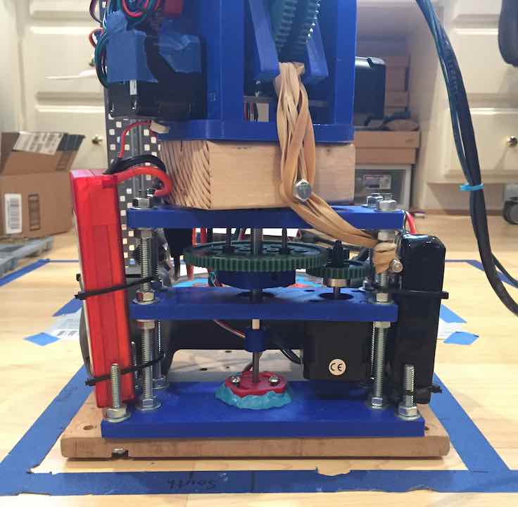
3D-Printed Planetary Gearbox
Since stepper motors don’t directly have enough torque to drive the arm, I had to use a gearbox to increase the torque. Doing some calculations, I needed around a 4:1 or 5:1 gear ratio. This meant a planetary gearbox would likely work best. The issue was the size constraints I was dealing with. Most stepper motor gearboxes were taller than they were wide, but I needed a flatter gearbox. Wanting to learn how to print custom gears, I decided to try my hand at designing one myself.
Doing some research, I chose to use herringbone gears for their high load, low noise capabilities. The issue was that these gears aren’t natively supported in Fusion 360, but there’s a plugin. To make a herringbone gear, I just made two helical gears that were mirrors of each other and combined them. The ring gear was a little trickier due to tolerances, but I found that scaling the gear up by about 1.01 provided a perfect fit with the planet and sun gears. The gearbox was layered, including separating the ring gear into two helical gears, to aid in assembly.
Structure
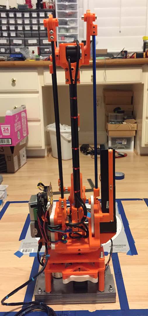
Structurally speaking, I started by reusing the 10 lb. sheet steel base. Since v3 had stiffness issues, I switched to using carbon fiber tubes for the arm material. Instead of drilling holes in the tubes, I designed clamps to mount them. Favoring modularity, I used the same encoders and gearboxes for everything. The parts for the parallel mechanism all used standard skateboard bearings and old aluminum and fiberglass arrows I had lying around. My carbon fiber arrows were reserved for v3, which was being kept as a backup. Everything was pretty much held in place using a screw at some point or another. All the moving parts were supported by bearings and hardened steel shafts. Looking back, most of these parts actually came from me wanting to build a 3D printer during the next summer.
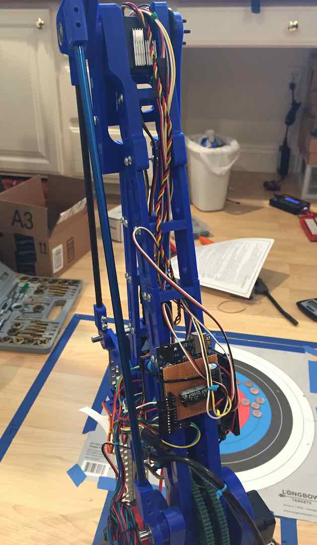
Electronics
With the mechanical designed worked out, I got to work on the electronics. The first step was to pick stepper drivers. One issue I ran into with v3 was that the cheap DRV8825 drivers I was using broke often, likely due to having a high load and bad cooling. Coupled with the fact that the NEMA 23 motor I was using needed about 4.5A, far higher than the 2A limit of the DRV8825, I definitely needed to look for new stepper drivers. Looking on Amazon, I learned about the popular TB6600 board. After much trial and error, I found out that the standard cheap design couldn’t supply above 2A, which was only ok for the NEMA 17 powered joints. Eventually I learned that buying the board that didn’t look as professional was the one that could actually supply 4A.
One issue I had with v3 was processor speed, which was due in part to my relative lack of coding experience at the time. To fix this, I bought the fastest Arduino supported board on the market at the time, the Teensy 3.6. It has interrupts on all pins, so I could hook up multiple encoders without worry. It was also blazingly fast, so I didn’t have to worry about analog reads and calculations.
Wire management was also pretty interesting since I didn’t account for it in the mechanical design. I really liked how I fit the wires for the end effector inside the carbon tubes. For the rest of it, I just used a bunch of zip ties and cut wires exactly to length.
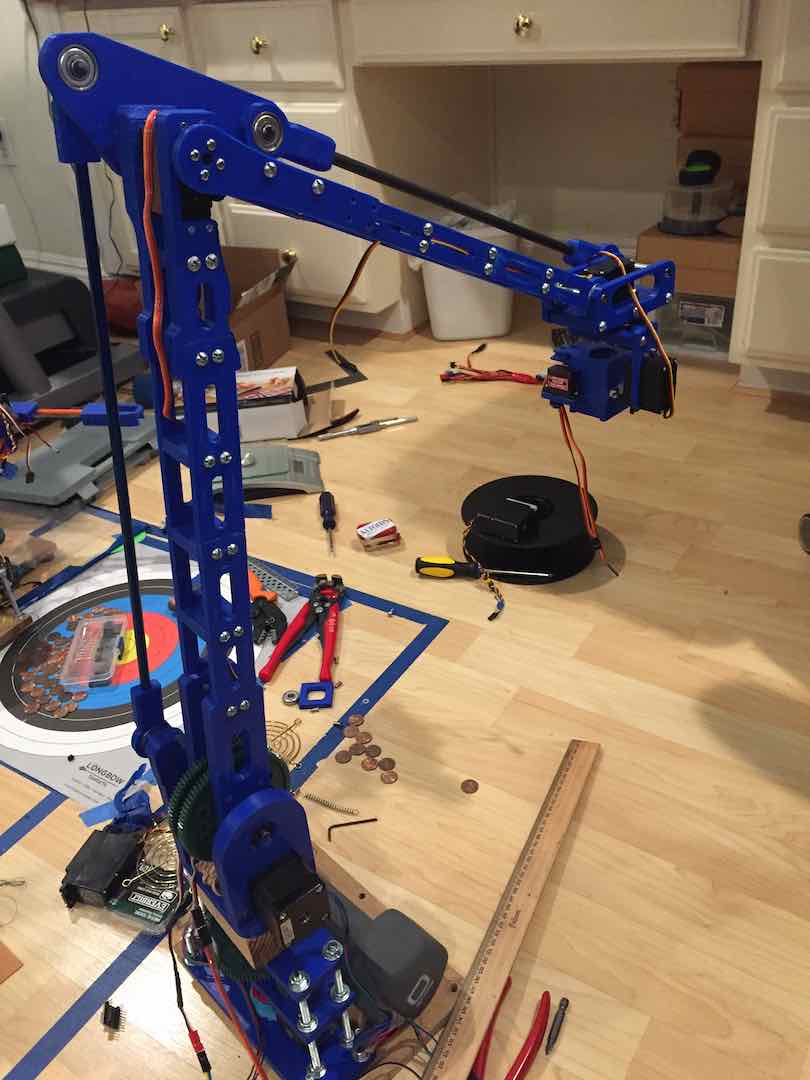
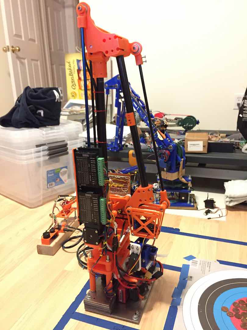
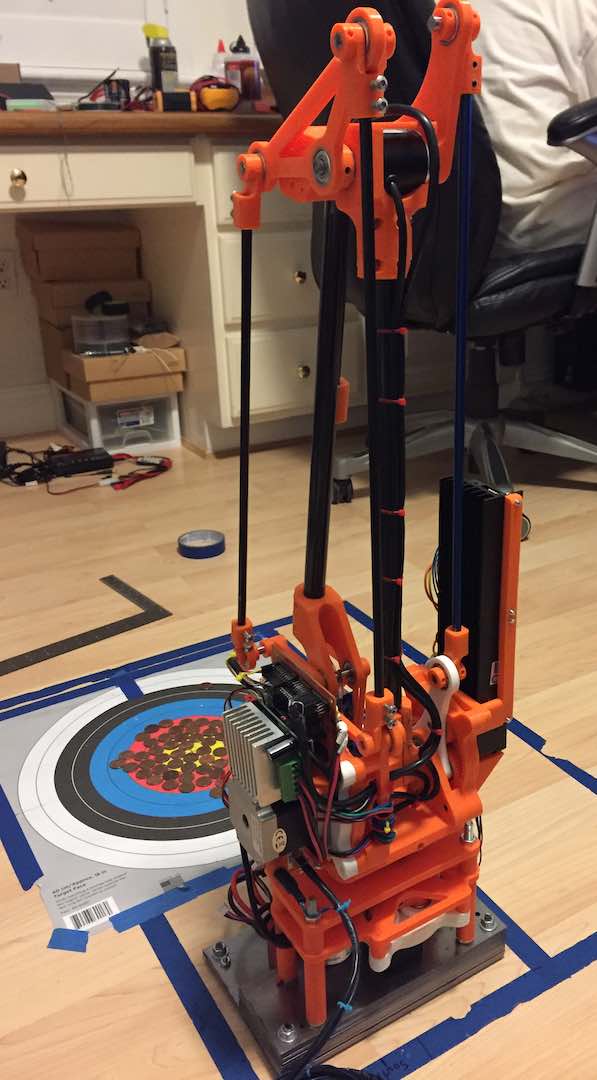
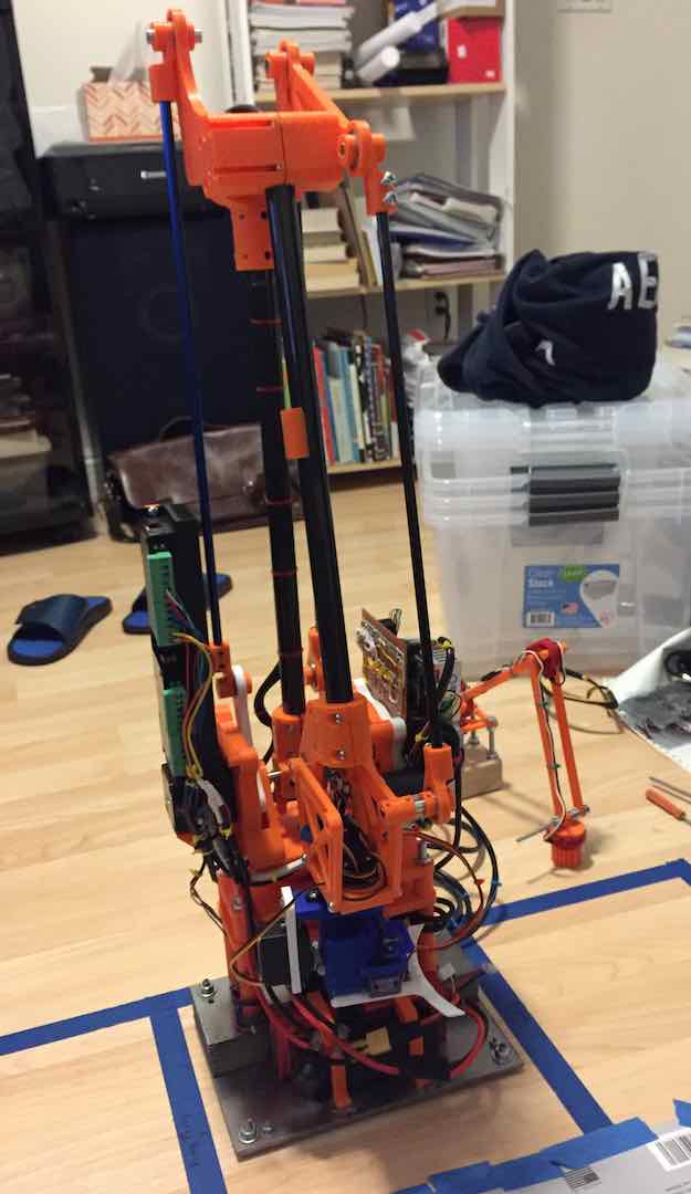
Putting It All Together
Here’s some pics of the completed robot arm. I did make some changes over the course of the year, like trying out new materials like PETG and Alloy 910. I also made a bunch of backup parts.
Competition
At Nationals, my heart was racing during the entire 3 minute run. Despite my countless hours practicing and improving the robot, I was still nervous. At the end of it, I was left with a sense of accomplishment and a 2nd place medal. The task was far more difficult than last year, so I was glad that I could still compete with the best of the best. What’s pretty cool is that Nationals was held at Wright State University in Dayton, Ohio, which was where it was held when I was in 7th grade, so a lot of great memories came back.
Earlier in the year, Troy went to the Golden Gate SciOly invitational at Berkeley. It was held at the same time as our Regional competition, so we sent our B team there. They didn’t have a robot arm to use, but thankfully I hadn’t taken apart v3 yet. With only the night before to learn about the arm and practice using it, they got 1st! I saw that as an absolute win.
Anyways, here’s a video of my run at Nationals.
Here’s a video of one of my practice runs earlier in the year. It’s better quality, but I did mess up a bit.

Comments