
Lightsaber v4
Written 8-31-19
During my dive into making PCBs for SMD components, I decided to see how small I could make a lightsaber. Since I was working on SciOly at the same time, I couldn’t spend much time on it. With this next version, I decided to make the electronics easily removable and repairable. I didn’t want to cut the metal casing this time, so I had to figure out a way to hide the switches underneath it. Looking back, this is probably simultaneously the cleanest design I’ve done internally and externally but also the most randomly thrown together.
Picking Components
Being a random project done in a very short time frame, I didn’t have time to handpick what electronic components I wanted to use.
First, I had to figure out what processor I wanted to use. Using a butane torch lighter (don’t do this!) and some careful heating, I was able to desolder the Atmega328P-AU off of an Arduino Pro Mini. Then, using some fine soldering skills, I attached wires in the right places to test the chip.
Next, I picked the motion sensors. I didn’t have a spare accelerometer lying around, so I used some vibration sensors from Adafruit. The heavy sensor was good for clashes while the light one was good for swings. Of course, using an accelerometer and measuring the acceleration vector’s magnitude would have worked far better. Sadly, I didn’t realize this until years later.
For the microSD card holder, I repurposed an adapter by soldering wires to it. It worked really well and was relatively easy to bring into CAD. Of course, using an actual microSD holder that is soldered to the PCB would be more reliable and easier to use.
Last I had to figure out the hidden switches. I recently learned about capacitive switches and wondered if they could work through a metal casing. It’s possible to use two metal layers and sense the capacitance between the two, but this proved difficult to get working since the capacitance was so small. One thing I noticed while trying to get capacitive switches working was that the case flexed ever so slightly when pressing it, enough to short the sense pin to ground. Thus, I didn’t need a capacitive switch anymore. Just squeezing the case and doing a digitalRead() would work.
Blade Construction
The blade was very similar in construction to v1-3 except this time I used about a hundred leftover UV LEDs to make a purple blade. One thing I failed to account for was that polycarbonate filters out UV, so the blade ended up being pretty dim.
I also used some clear gift wrap on the outside to create a smooth look when the blade was off. The LED string is wrapped with thin packing foam and wrapped tight with clear packing tape. Compared to my other blades, this one has the most even diffusion.
Assembly
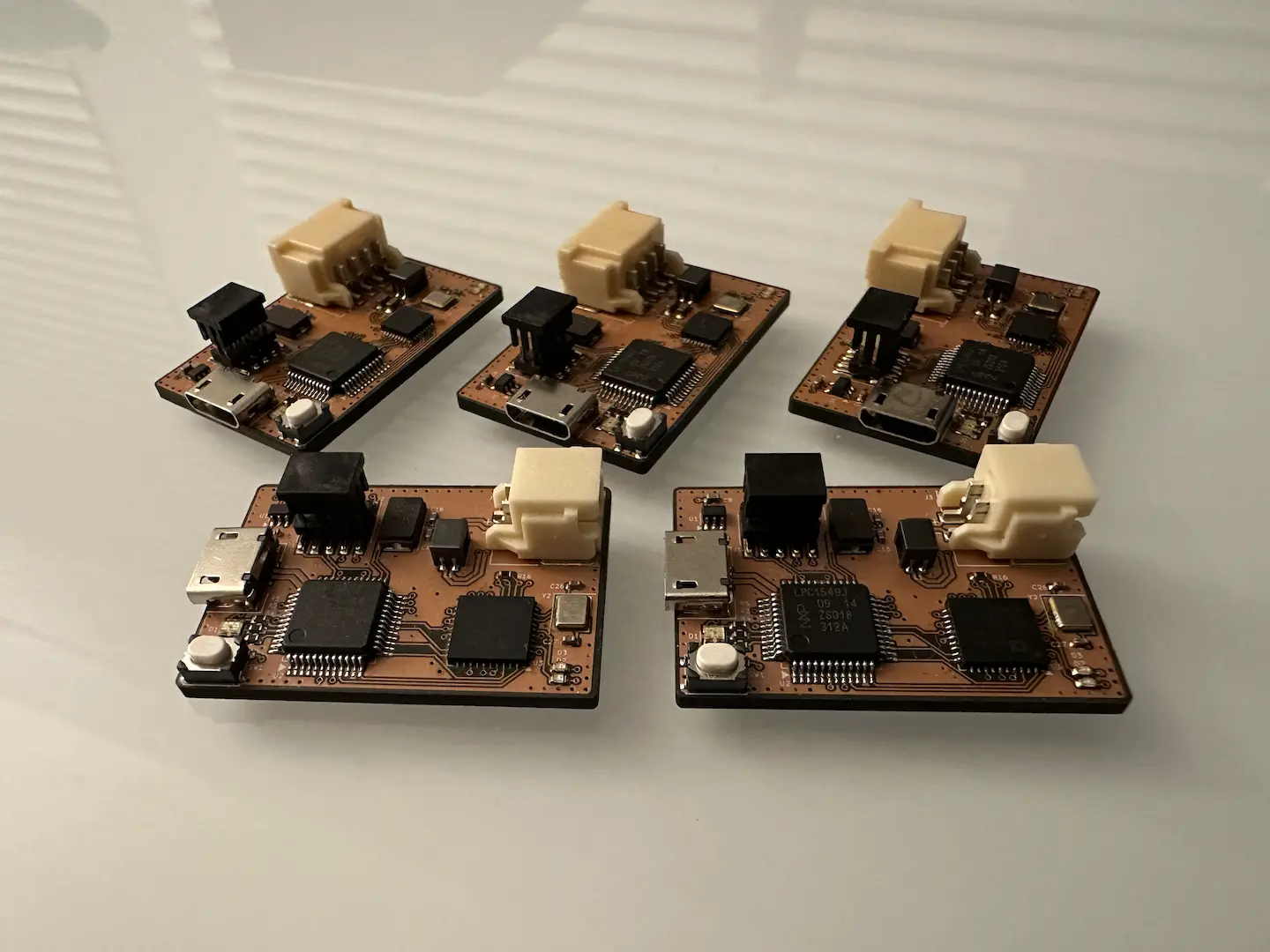
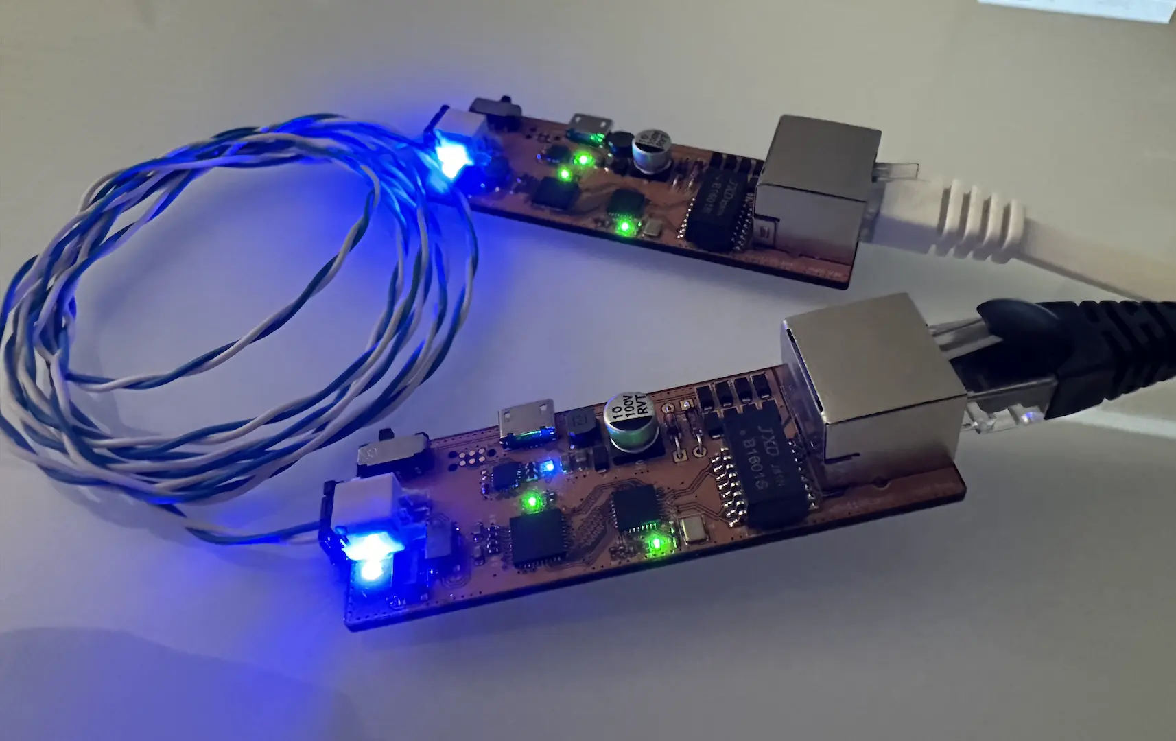
Once the electronics were more or less done, I designed the PCB using EasyEDA. Then I milled it using my CNC mill, which worked pretty well because of the 13 mil spacing. After some soldering, I ended up with this.
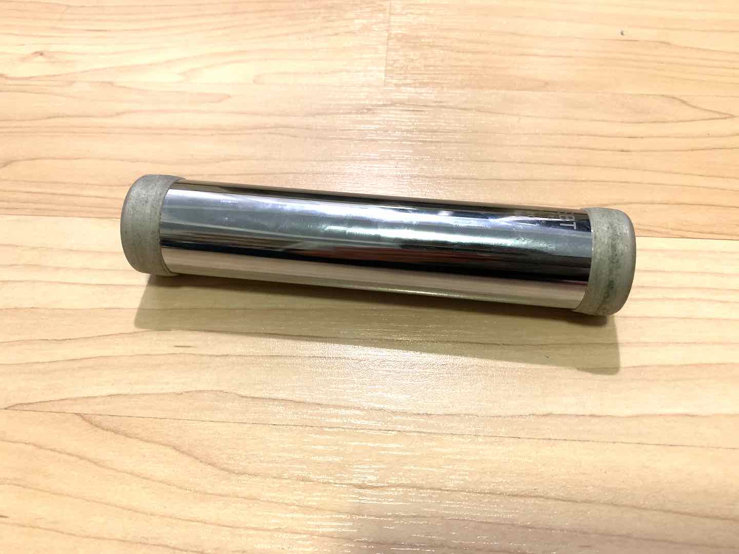
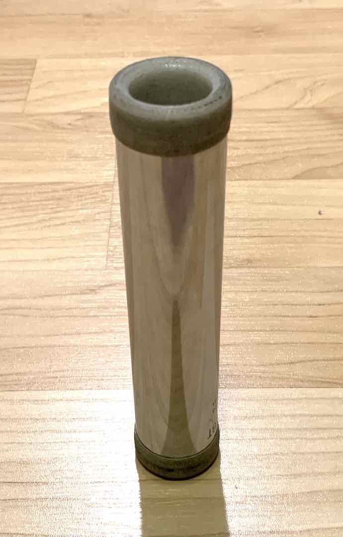
Then I brought everything into Fusion 360 to design the internal chassis of the lightsaber. What’s pretty cool is that I measured the threads on the chrome sink tube I would be using as a case in order to design caps that would screw onto the ends but not be bulky.
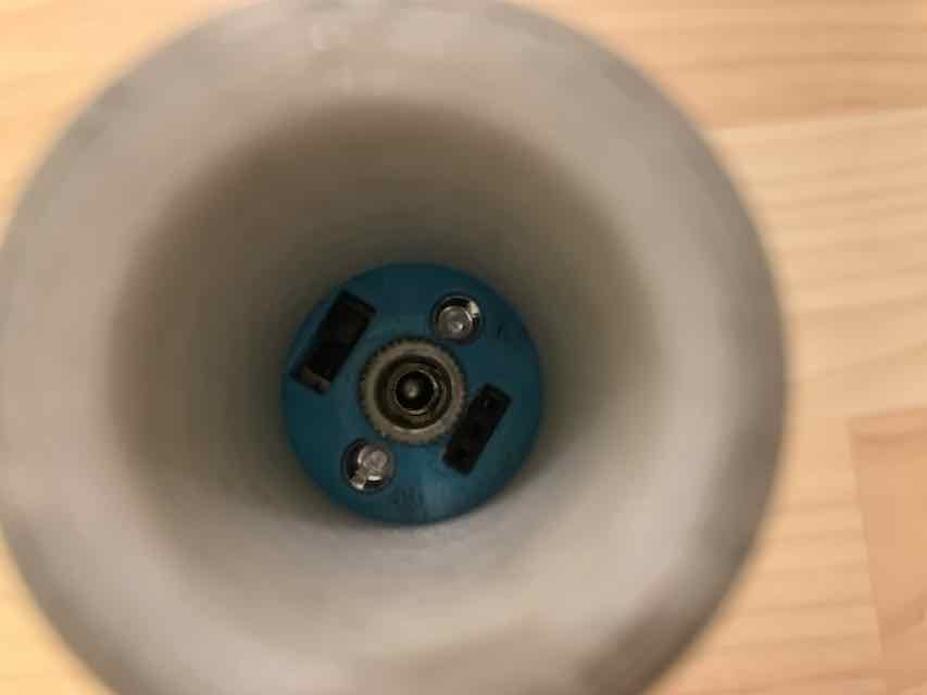
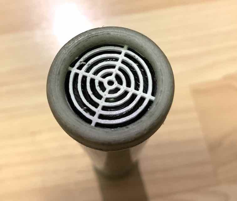
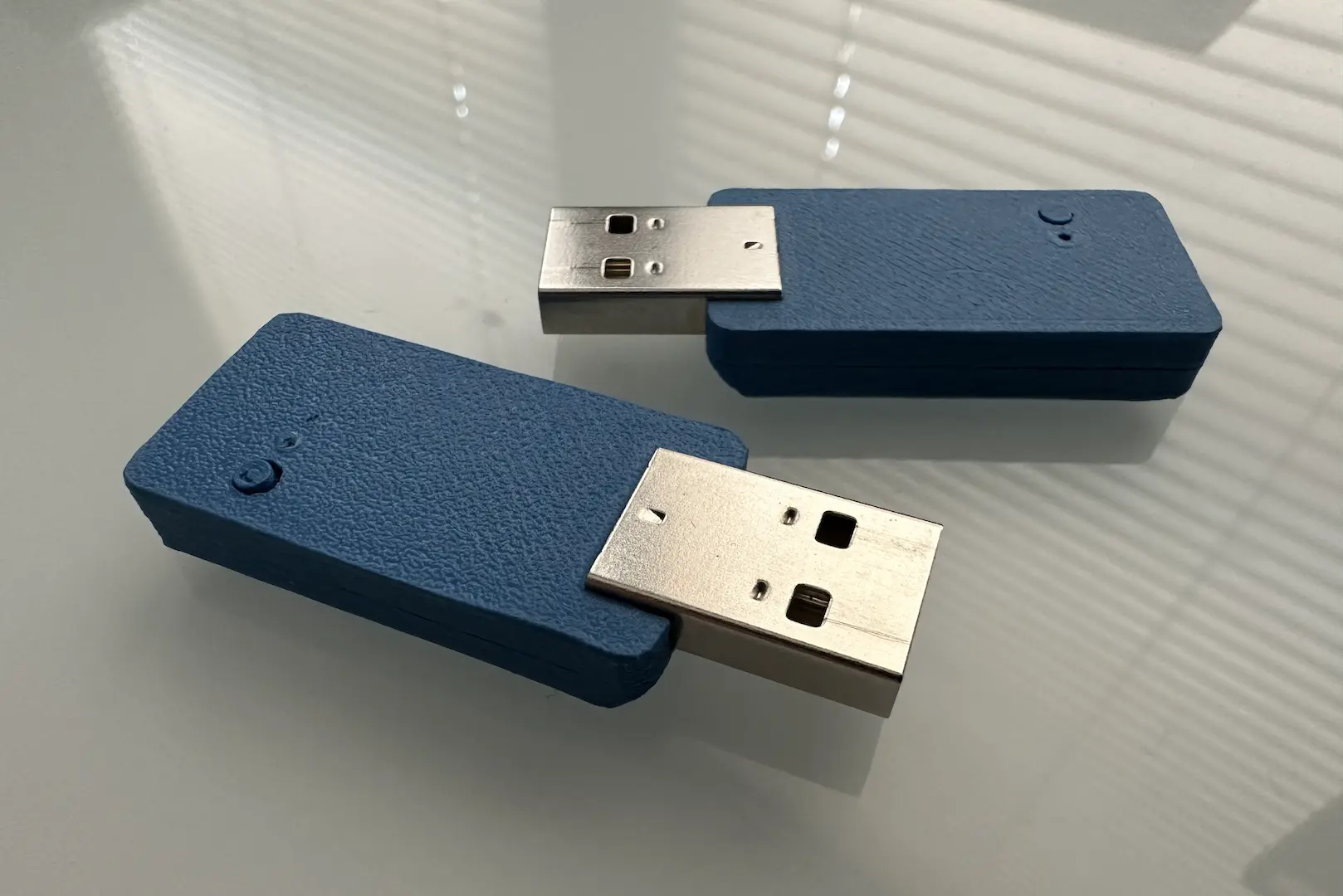
After I did some printing and assembly, the internal assembly looked something like this:
Code
I pretty much just repurposed my code from v3. I did have to make some changes to work with the Atmega328 instead of the Atmega32u4. Here’s the v4 code.
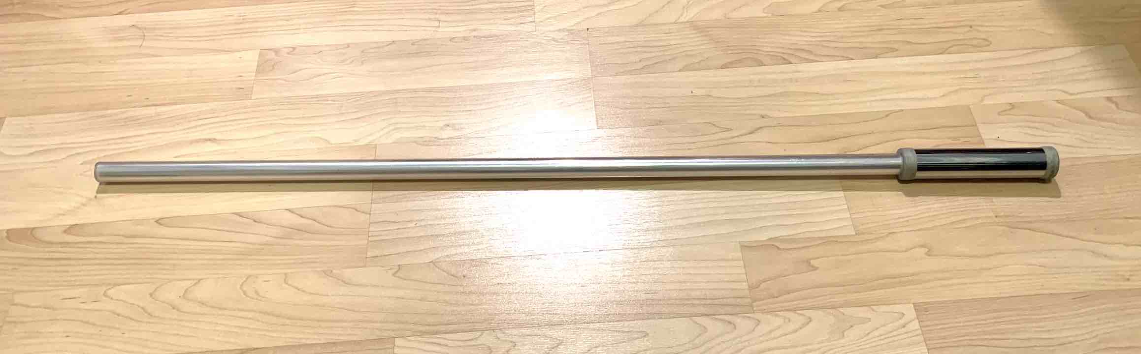
At the end of the day, this ended up being the smallest lightsaber I ever made. It wasn’t necessarily the most reliable or loudest or brightest or easiest to operate lightsaber of the bunch, but it was a solid application of what I was trying to teach myself at the time.

Comments