DIY DC Current Clamp
Written 8-18-19
While competing at RoboSub this year (our 1st year competing!), one of the things we realized was that we likely seriously overestimated the current demands of our sub. At competition we realized that, even after a whole day, we barely depleted one of our 4 batteries. Thus, we decided that one of the things we needed to do next year was determine power draw with actual current measurements. Total current draw will probably still be in the 10s of amps, and since we definitely don’t want to deal with using current shunts in the tight electronics enclosure of our sub, I wondered about using those current clamps that I’ve heard about.
As it turns out, DC current clamp meters are widely available on Amazon. As usual, I began to wonder how they worked since DC current doesn’t generate a changing magnetic field. A quick Google search later and I found out that these meters cleverly use a Hall effect sensor to measure the strength of the magnetic field. Thus, I decided to put together a little prototype.
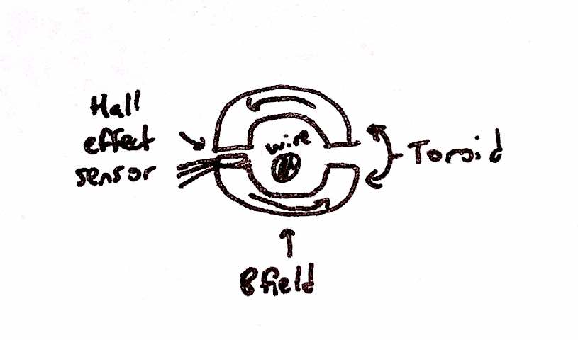
The basic composition of a DC current clamp is a ferrite toroid, cut in half to fit a wire through, and a linear Hall effect sensor. The toroid “captures” the magnetic field from the wire and directs it straight into the sensor. It’s a pretty neat way of noninvasive current measurement.
Build
Before doing any CAD or finalizing any design, I needed to make sure the theory actually worked. I took the largest ferrite toroid I had and chopped it in half with a hacksaw. I soldered some wires onto a 49E linear Hall effect sensor and hooked it up to an Arduino outputting the analog readings to the serial monitor graph. One hand holding all the parts around the battery wire of my RC car, other hand on the remote, and eyes on the screen, I was delighted to see the readings change as I revved the RC car. (I also realized how much noise a brushless motor puts into the system, something we’ll consider more in-depth next year for the sub.)
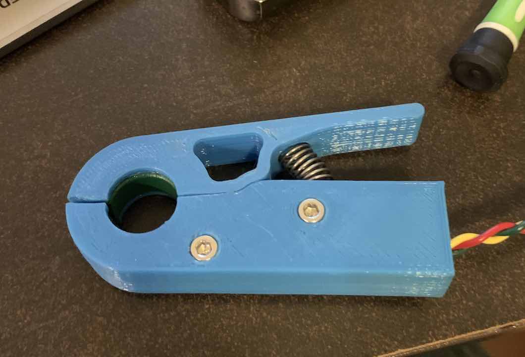
Next, I modeled a basic clamp in Fusion 360. I still had to determine the amplifier requirements and whether to use an example circuit I found online or one of my own design. I printed out my design and proceeded with prototyping the circuit.
To improve usability and reliability, I ended up designing my own circuit based off of one I found online. I made the gain adjustable as well as the reference voltage on the non-inverting input of the opamp. I added resistors around the potentiometer to make finely adjusting it easier. Since making PCBs is pretty easy now, I threw the circuit into KiCad.
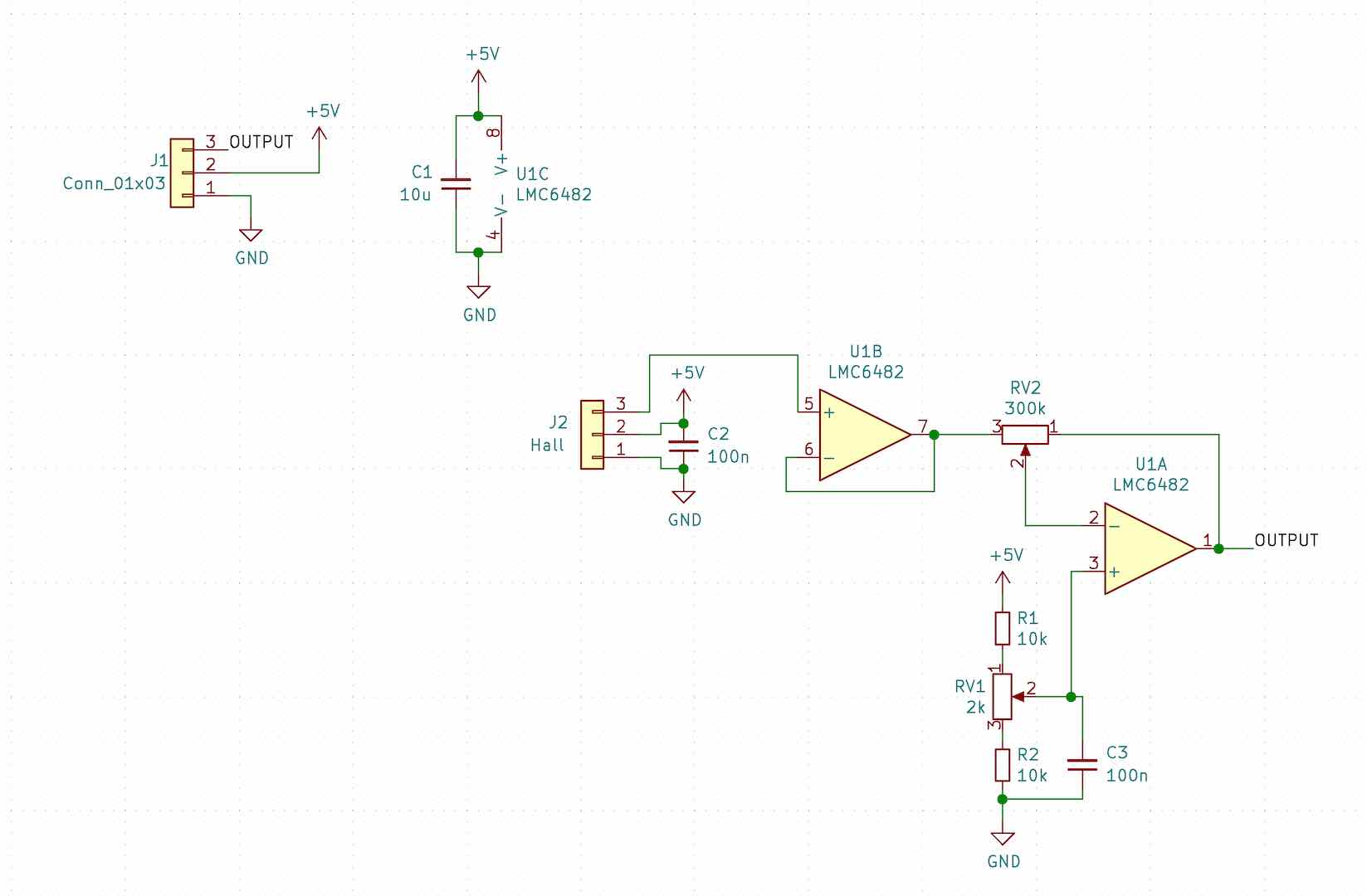
I did my best to design the circuit to reduce noise because we are making pretty fine measurements.
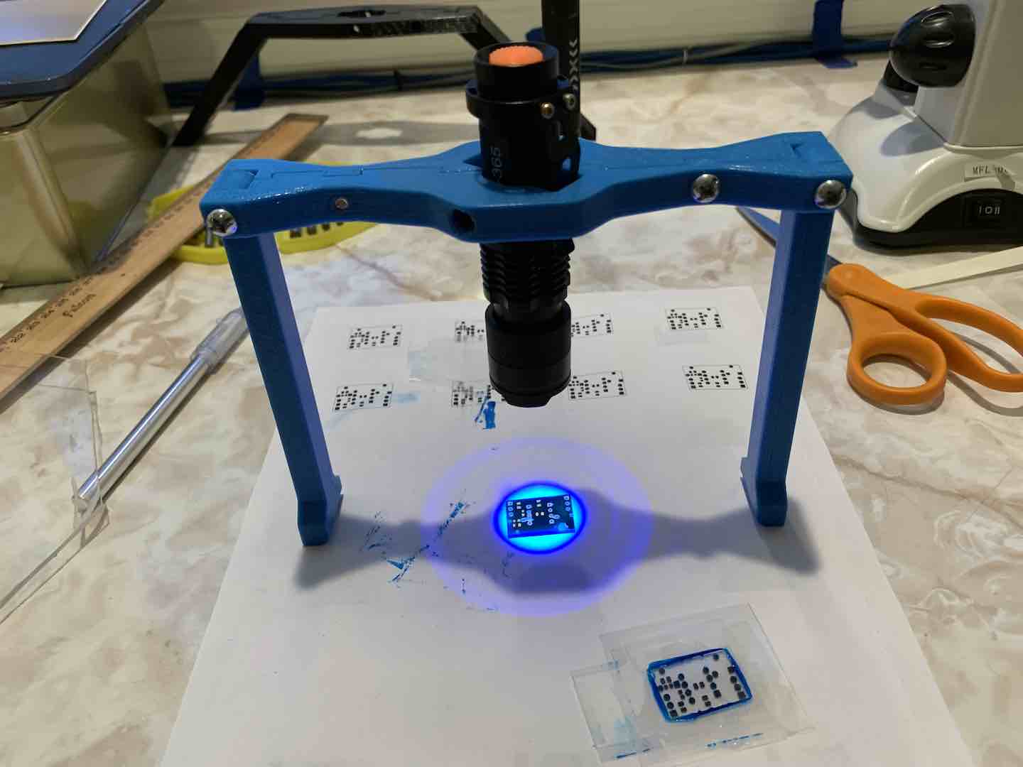
I also tried doing a DIY soldermask for the second time and it actually worked pretty well.
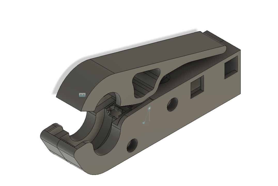
I updated the clamp design with the observations I made while using the prototype and also made room for the circuit board.
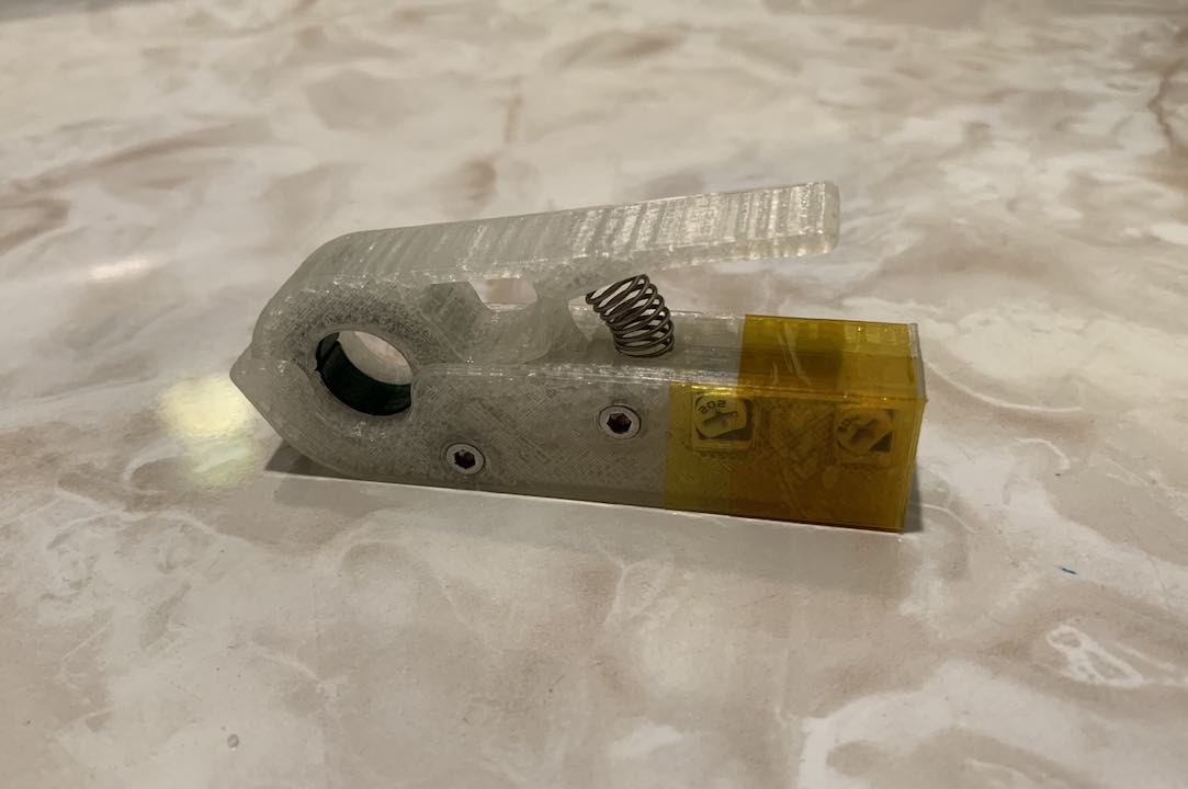
Calibration & Code
First things first, I adjusted the potentiometers so that the range of the meter was around 100A. I jacked up the gain to accentuate small voltage differences to make it easier to adjust the reference voltage on the non-inverting input of the opamp. After setting the reference voltage so that the output is roughly around 2.5v with no wire clamped, I used my battery charger to provide a 5A reference current to help adjust the gain.
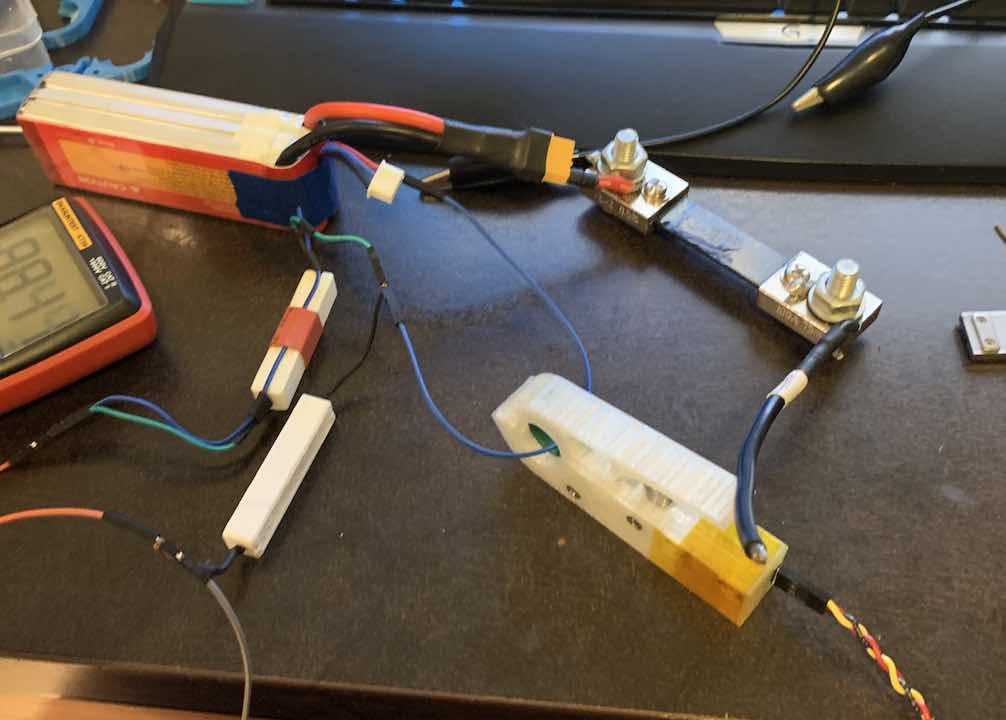
Next thing to do was to gather a bunch of data points. I didn’t have any accurate current sources so I jerry-rigged a setup with a current shunt, some lithium batteries, and a power resistor. I made sure to be as safe as possible, but I still wouldn’t recommend doing what I did for safety reasons.
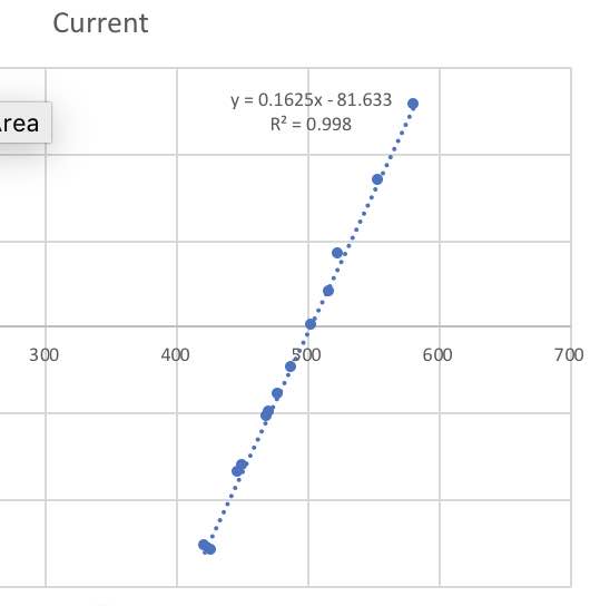
After all that was done, I wrote a simple Arduino program to put everything together.
#define BUFFER_SIZE 512
#define READ_PIN A0

#define CENTER 503.2 //reading at 0A
#define SLOPE 0.1625 // in Amps/Reading
/*
 * To Perform Reading:
 *  1. Probs wanna rough calibrate against known current
 *  2. Angle changes CENTER for some reason, so hold at angle u wanna measure
 *     and update CENTER
 *  3. Do the reading.
 */

void setup() {
  Serial.begin(115200);
}

void loop() {
  float r = getReading();
  Serial.print("Raw: ");
  Serial.print(r);
  Serial.print("\t Current(A): ");
  Serial.println((r - CENTER) * SLOPE);
  delay(1);
}

float getReading() {
  long tot = 0;
  for (int i = 0; i < BUFFER_SIZE; i++) {
    tot += analogRead(READ_PIN);
  }
  return 1.0 * tot / BUFFER_SIZE;
}
At the end of the day, I ended up with a decently accurate (±0.5A) device. It definitely won’t replace one I can buy off Amazon but for a total cost of around $1, it’ll do the job just fine for now. And it was an awesome learning experience.


Comments