Setting Up the CAN Bus on STM32
Updated 2-1-2021
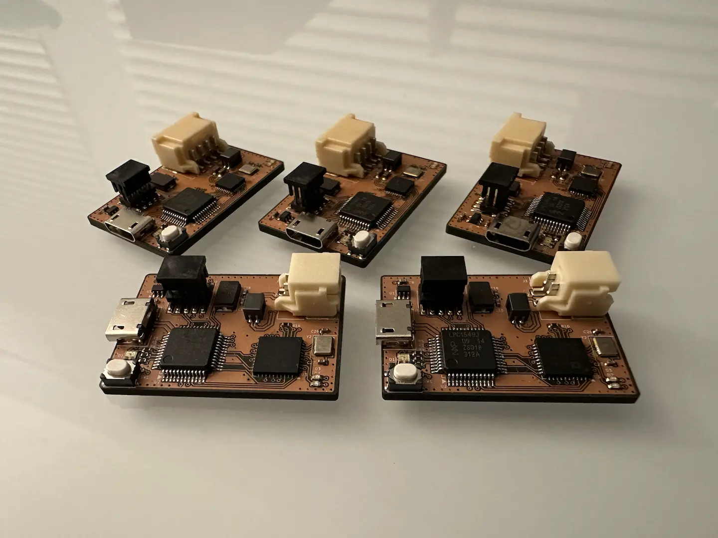
The ubiquitous CAN bus is found in just about every car today and in more places than you’d expect. It’s extremely robust, reasonably fast, uses only two wires, and can connect many different nodes. After receiving samples of a TCAN332G CAN transceiver from TI, I decided to figure out how to use it.
Hardware
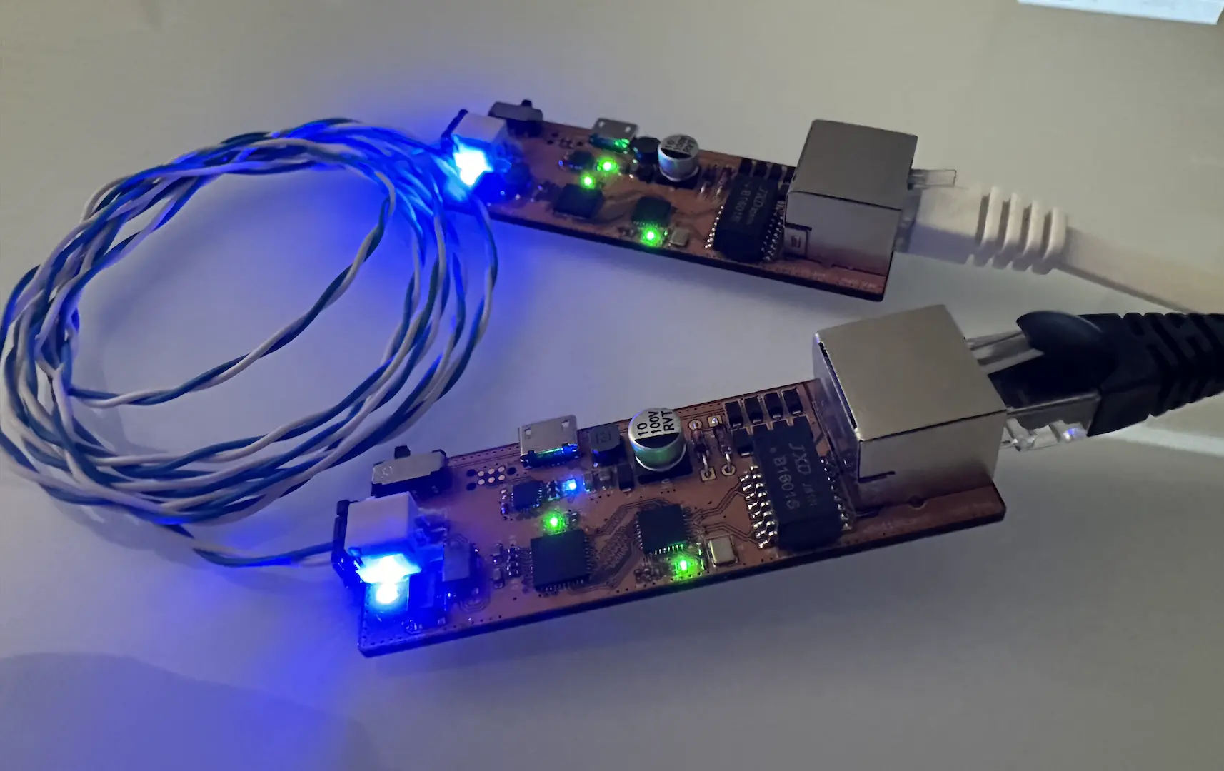
When it comes to necessary hardware, the most important thing is the CAN transceiver which converts the TX and RX lines from the microcontroller to the differential CANH and CANL lines. The wiring should be a 120Ω characteristic differential impedance with 120Ω terminating resistors on both ends to prevent signal reflections. In practice for getting something basic working on the bench, you can get away with random wires.
It’s actually possible to not use a transceiver by using some diodes and following this schematic instead, That’s what I used to do a sanity check using a Teensy 3.6 while I was making breakout boards for the TCAN332G.
Mbed
When it comes to working with ARM microcontrollers, Mbed provides a very low barrier to entry. It’s not quite as easy as Arduino, but it’s definitely easier than STM32CubeIDE. As is usually the case, the simplicity does come at the cost of flexibility when doing certain things. Mbed Studio has made huge improvements since I first made this post so I’d recommend it for anyone especially if they’re just starting out. That and I’m also not a fan of needing Internet connectivity for software development.
Not every STM32 chip is supported in Mbed, but most of the popular ones are. Also note that as long as you keep an eye on flash size and memory usage, code amongst any one family is intercompatible. For example, code for the target NUCLEO-F103RB also works for the popular STM32F103C8T6.
To show just how simple Mbed is, let’s start by initializing CAN.
CAN can(PA_11, PA_12, 1000000); // RX, TX, baud rateLet’s send a CAN message.
char data[] = "Hello!"; // 6 chars

// verbose way
CANMessage msg;
msg.id = 127; // 11-bit ID (can be changed to extended 29-bit)
msg.data = data; // points to char array with data to send
msg.len = 6; // number of bytes to transfer, up to 8 for normal CAN
can.write(msg);

// one-liner way
can.write(CANMessage(127, data, 8));
Receiving messages in a polling fashion is just as easy, so I’ll leave that as an exercise for the reader. Let’s spice things up by doing it with interrupts instead. As of Mbed OS 6.5, the CAN implementation tries to acquire a lock before actually reading a message, but locks can’t be acquired in an interrupt context. As a result, the cleanest fix I found was to make a subclass of CAN that doesn’t acquire this lock and use that instead.
class IRQ_CAN : public CAN {
    using CAN::CAN;

    public:
        int read(CANMessage &msg, int handle=0) {
            int ret = can_read(&_can, &msg, handle);
            return ret;
        }
};
Now we can attach a function to be called every time we receive a CAN message.
void rxIrq() {
    CANMessage msg;
    can.read(msg);
    // do something
}

can.attach(rxIrq); // place this somewhere like main()
Keep in mind this is an interrupt context, so if you don’t want the rest of your program to stop for too long while servicing it you should keep the computation to a minimum. Setting a flag and having a message queue is probably the simplest option. Offloading it to a Thread and EventQueue is another option. If you still want to keep everything in the interrupt, you can even use the NVIC to ensure other interrupts are prioritized.
Recently, Mbed Studio expanded support for the STLINK programmers, so we can actually compile, upload, and even debug code all inside Mbed Studio. However, if you have an unsupported programmer, the compiled binaries are available in the BUILD folder.
STM32CubeIDE
STM32CubeIDE is my go-to IDE for using features of STM32 chips that Mbed doesn’t make as easy. The history of ST’s recommended IDE is quite interesting and I still remember switching from SW4STM32 to Atollic TrueSTUDIO to STM32CubeIDE 1.0.0.
STM32CubeMX
Nowadays STM32CubeMX is builtin to STM32CubeIDE which is really convenient. After making a new project and choosing your microcontroller, you’ll get a menu to configure many aspects of the boilerplate code generation. The things I usually start out with are configuring the clock under “System Core > RCC” and “Clock Configuration”, and enabling debugging under “System Core > SYS”.
Next let’s enable CAN under “Connectivity > CAN”. The prescaler divides the APB1 peripheral clock before it gets input to the CAN peripheral. Every bit period in CAN is divided up into time quanta and we sample partway through. Check out this website for a better explanation and a calculator for the values. Essentially we want to pick our Segment 1 and Segment 2 time quanta such that the total bit time matches our baud rate. Note that STM32CubeIDE might say a valid configuration is invalid due to floating point rounding error.
If you’re using receive interrupts, make sure to also enable it under the “NVIC Settings” tab. Also enable CAN callback registration in “Project Manager > Advanced Settings”. As with before, reading CAN messages without interrupts is left as an exercise for the reader. The libraries are well documented with comments.
Code
After saving and generating the boilerplate code, we can initialize CAN. In order to receive messages, we need to setup a CAN filter which controls what messages are allowed through and to which FIFO they’re stored. The following code lets all messages through and puts them in FIFO 0. It also starts the CAN peripheral and attaches the receive interrupt to call can_irq(). Place this in MX_CAN_Init(). Note that hcan might be hcan0 if your chip has two CAN peripherals.
  /* USER CODE BEGIN CAN_Init 2 */

  CAN_FilterTypeDef sf;
  sf.FilterMaskIdHigh = 0x0000;
  sf.FilterMaskIdLow = 0x0000;
  sf.FilterFIFOAssignment = CAN_FILTER_FIFO0;
  sf.FilterBank = 0;
  sf.FilterMode = CAN_FILTERMODE_IDMASK;
  sf.FilterScale = CAN_FILTERSCALE_32BIT;
  sf.FilterActivation = CAN_FILTER_ENABLE;
  if (HAL_CAN_ConfigFilter(&hcan, &sf) != HAL_OK) {
    Error_Handler();
  }

  if (HAL_CAN_RegisterCallback(&hcan, HAL_CAN_RX_FIFO0_MSG_PENDING_CB_ID, can_irq)) {
    Error_Handler();
  }

  if (HAL_CAN_Start(&hcan) != HAL_OK) {
    Error_Handler();
  }

  if (HAL_CAN_ActivateNotification(&hcan, CAN_IT_RX_FIFO0_MSG_PENDING) != HAL_OK) {
    Error_Handler();
  }

  /* USER CODE END CAN_Init 2 */
Now let’s transmit a message.
uint32_t mb;
CAN_TxHeaderTypeDef msg;
uint8_t data[] = "Hello!";

msg.StdId = 127;
msg.IDE = CAN_ID_STD;
msg.RTR = CAN_RTR_DATA;
msg.DLC = 6;
msg.TransmitGlobalTime = DISABLE;

if (HAL_CAN_AddTxMessage(&hcan, &msg, data, &mb) != HAL_OK) {
  Error_Handler();
}
Now we’ll write the message received callback, equivalent to rxIrq from above. I placed the following in “USER CODE BEGIN 4”.
void can_irq(CAN_HandleTypeDef *pcan) {
  CAN_RxHeaderTypeDef msg;
  uint8_t data[8];
  HAL_CAN_GetRxMessage(pcan, CAN_RX_FIFO0, &msg, data);
  // do something
}
Explore the HAL CAN library if you want to learn about other settings and what not. Like Mbed Studio, we can build, program, and debug our code from within the IDE. It searches for an STLINK by default, but you can also setup a J-Link or even OpenOCD.
And that’s about it. The basics of what you need to know to get CAN up and running on STM32. I haven’t gotten my hands on a CAN FD enabled chip yet so that’s next.


Comments