
MMv2
Way back in January, after finishing Concept Micromouse v1, it was time to head back to Berkeley. There, I set about finalizing my design into something other students could potentially manufacture. It would also be an interesting opportunity to make use of campus resources to bring a project from start to finish.
Hardware
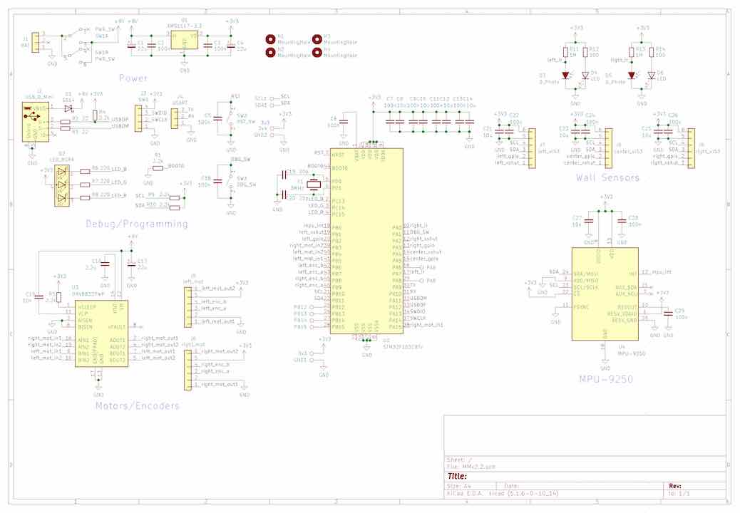
Considering the various modifications I wanted to make to the previous design, I essentially started the whole PCB design process over from scratch. Well, I did get heavy inspiration from the previous design. Here’s a somewhat exhaustive list of changes.
- Changing VL53L0X side sensor angle from 22° to 27°. I experimentally determined this to be the optimal angle to center the cone of detection within two walls.
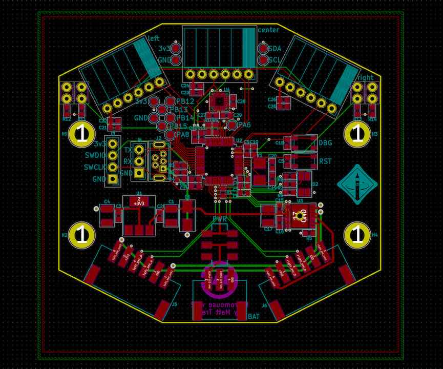
- Professionally made PCBs from JLCPCB (not sponsored). The quality is definitely not as good as Bay Area Circuits or OSH Park but certainly not bad for the price. My intent was to eventually get boards sponsored by Bay Area Circuits, so I designed the board to maximize panel yield.
- Added a tactile switch in my favorite PTS810 style package to have some kind of user input.
- Added an MPU-9250 IMU which aids positioning. However I might’ve damaged it while soldering.
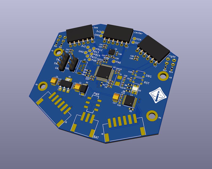
- Switched to right angle female headers to make the VL53L0X sensors easier to mount.
- Added a micro-USB port to enable use of a DFU bootloader. I didn’t end up using this as it’s less convenient than an ST-Link.
- Switched to a 2S 7.4v LiPo. This doubled the max speed to 1000mm/s but that was only because the motors were undervolted in the previous design.
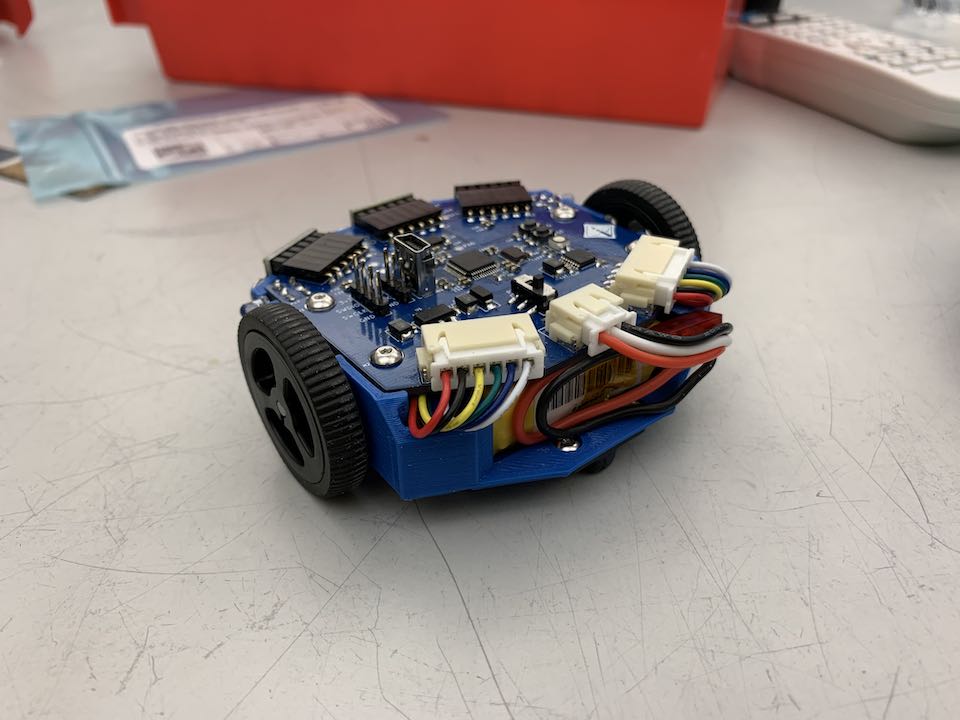
- Switched to JST-XH connectors for the motors to match the batteries. Ultimately this was a poor decision as the connector is bulky and overkill for the purpose.
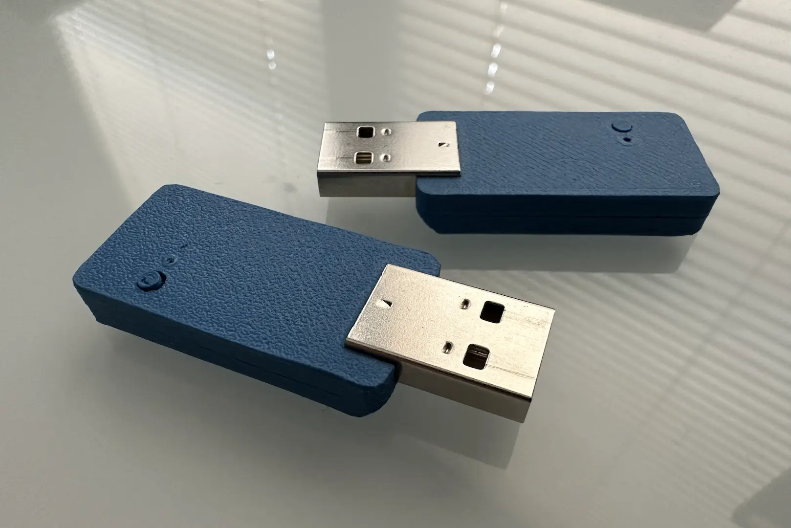
- New 3D-printed frame which I designed with a caliper this time.
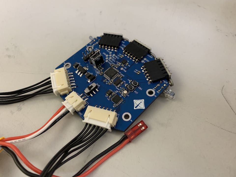
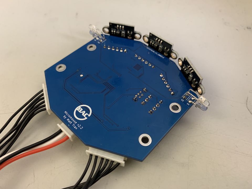
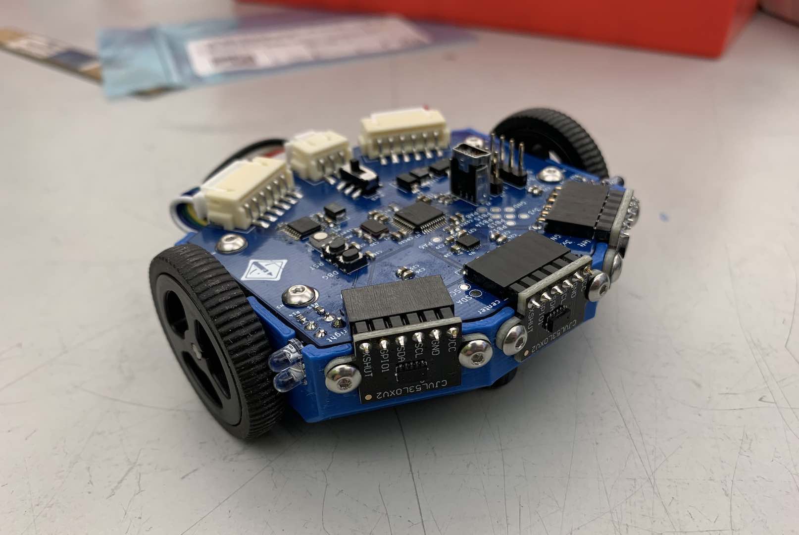
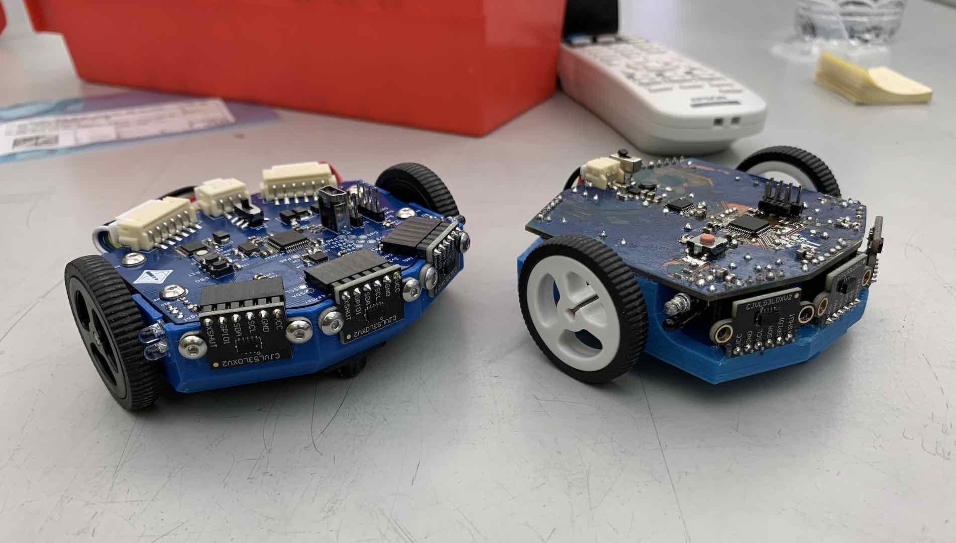
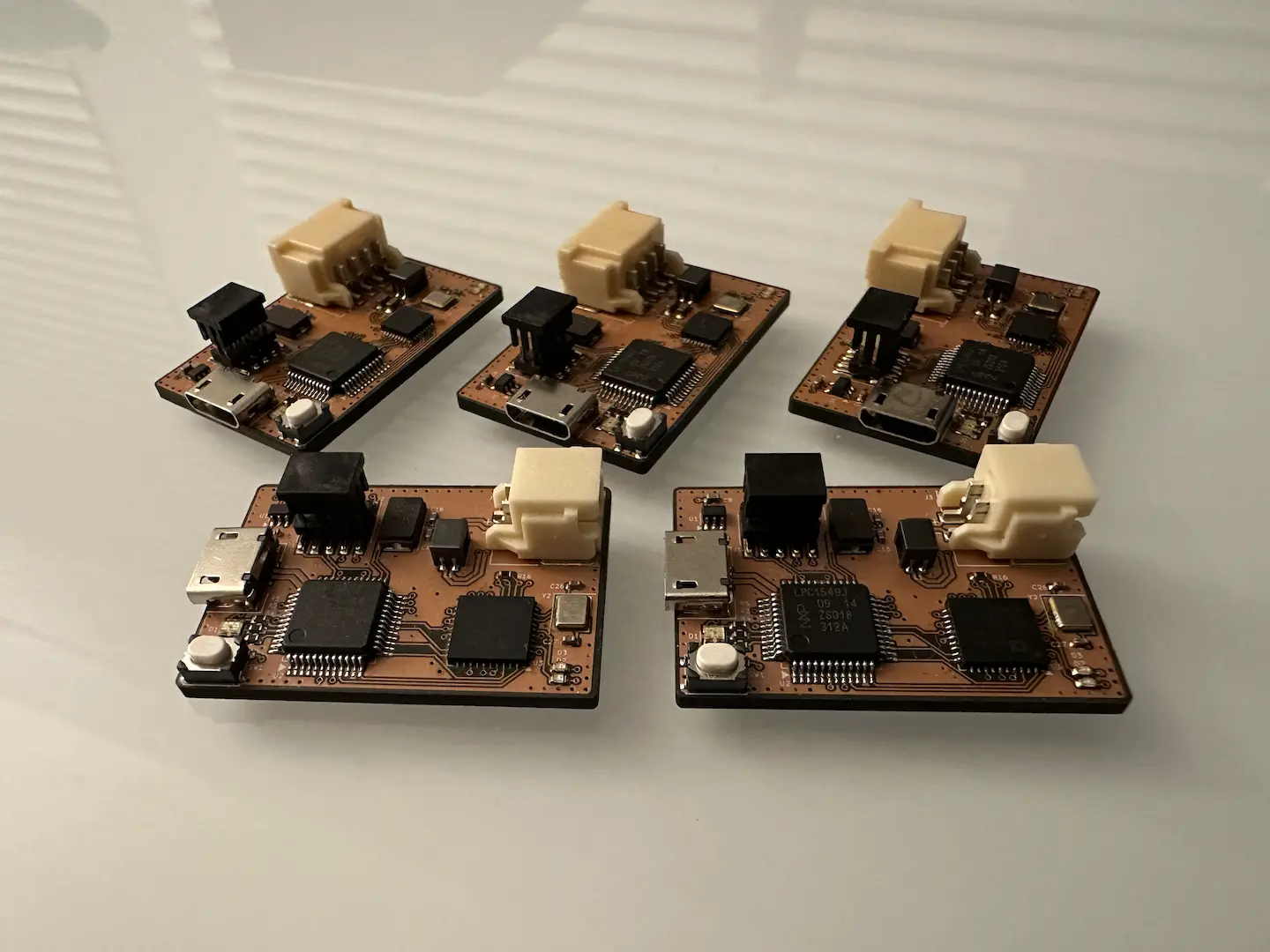
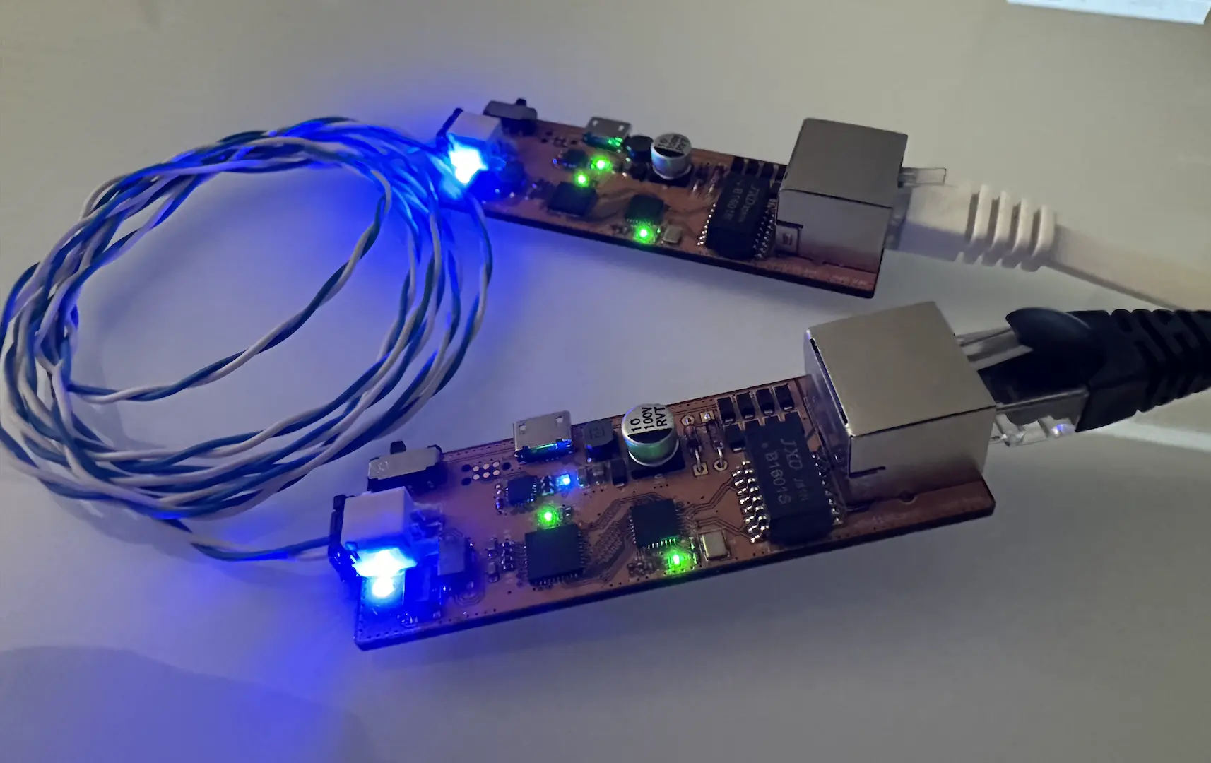
As usual, pics!
This was the first personal project I carried out from start to finish entirely within Berkeley and I’d say it went pretty well. Since I lived in Southside, I had to walk across campus every time I wanted to assemble anything. Other than that, the resources available at the Jacobs Makerspace were excellent and the staff are so nice, supportive, and experienced. However, I do still have a slight preference to my tools at home which are just a few steps away and open at 4am.
Firmware
After finishing the hardware, I headed straight to writing the firmware (which is the more technically correct term than software?). Since I just came off the whole actually starting to learn C++ train from doing CS170, I took a very object oriented approach to the whole thing. At the end of the day, I had a set of libraries that handled all of the sensor reading and motor control inside of interrupts and threads. This way all the user needs to do is provide the maze solving algorithm. MMSim is decent but I’ll need to add support for 45° turns.
The biggest thing I still haven’t done is also arguably the most difficult and tedious. It’s the positioning algorithms. Since I don’t have a physical maze I can test on yet, I’ve been putting it off to work on other projects.
Conclusion
While I certainly would not call this project a success because I still haven’t gotten to physical maze solving, it’s certainly a step forward. It boasts various improvements over the current design used to teach the DeCal while maintaining the same cost. The firmware design is a great starting point to build off of to finally finish maze solving. Just a great experience all around.

Comments