
100BASE-T1 Converter
https://github.com/dragonlock2/kicadboards/tree/main/breakouts/dp83tc811r https://github.com/dragonlock2/miscboards/tree/main/psoc_creator/100BASE-T1.cydsn
One of the interesting Ethernet variants is 100BASE-T1 which is used in the automotive space and offers full-duplex communication over a single unshielded twisted pair. The compromise is a far shorter maximum length at 15m. Since I had some 100BASE-TX PHYs leftover and Digi-Key had some 100BASE-T1 ones in stock, I decided to build a converter between them.
Design
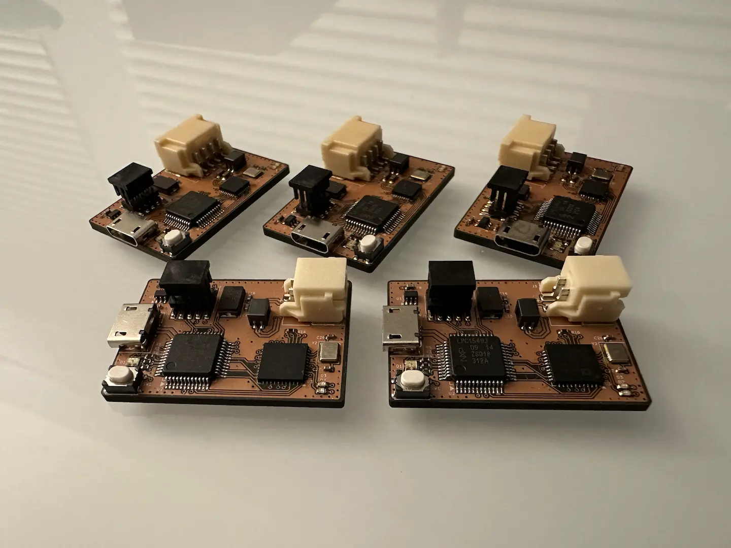
The hardware design was relatively straightforward with most of it coming from reference designs. I couldn’t find any designs with an RMII to RMII connection and had to infer based on the KSZ8091 back-to-back PHY configuration and MII to MII designs. As expected, the solution was to connect CRS_DV and TX_EN as well as the TX and RX signals together. They must also share a reference clock, although one PHY can be used to provide a master 50MHz clock for the other to reduce part count. For maximum configurability, I also made sure that all the strapping options were available. I also added a microcontroller to configure the PHYs over the MDIO bus.
Bring-up Hell
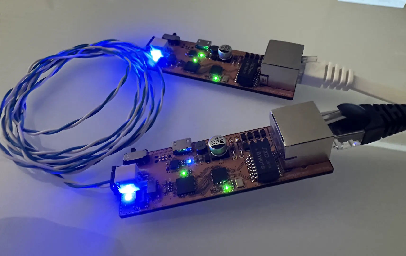
The board bring-up process was absolute hell. Since I don’t have any 100BASE-T1 devices, I connected two boards together to act as a 100BASE-TX passthrough. At first only the 100BASE-TX link up was working but no packets transferred and the 100BASE-T1 link wasn’t establishing. To help the debug process, I talked to the PHYs over a bit-banged MDIO bus (not the same as I2C!). I eventually learned that 100BASE-T1 (and the other automotive variants) define a commander and responder during the link up process after which full duplex communication is possible. Thankfully, that’s configurable over MDIO (as well as straps) and I finally got the 100BASE-T1 link working. Packets were finally transferred but with a 30-70% drop rate (the horror!).
The debug process from there was far from smooth. Thankfully, the KSZ8091 and DP83TC811R both have loopback options among all parts of the communication pathway. To reliably check packet drop rate, I sent ping requests and checked which ones made it (in both directions) using Wireshark. I started with an analog loopback on 100BASE-TX and checking the 100BASE-T1 signal quality to make sure my electrical layout side was good. I then started moving between enabling all the other loopbacks to see where the packets were being lost. After probing the RMII lines, I realized that CRS_DV was toggling at the end of a packet which was certainly not good if it’s piped into TX_EN. Thankfully both PHYs allowed switching to RMII Revision 1.0 to turn off that behavior. Still the problem persisted.
Next using local and remote RMII loopback I learned that the last two bits of each packet was randomly being dropped. Correlating this with the CRS_DV signal, the hold time slack on it was marginal. Part of this was due to REF_CLK being delayed over the PCB trace which I attempted to solve with a register – only documented in the KSZ8091 errata – that adjusted clock skew. This did not work. After trying all the other registers that adjusted signal timing and even adjusting the crystal load capacitance to shift the resonant point, I gave up and nearly considered cutting traces and adding wires to fix the timing.
Thankfully, I held off for just a bit longer before cutting traces. I first tried tying TX_EN high to avoid any timing issues which didn’t work. Then I noticed that at the beginning of each packet, the DP83TC811R would assert CRS_DV early by a seemingly random amount of time (since CRS and RX_DV are combined signals in RMII). Coupled with the fact that tying TX_EN high doesn’t work and that 100BASE-TX uses 4B5B encoding, I correctly assumed that the timing of the TX_EN signal matters. Since CRS was causing TX_EN to go high early, this resulted in the 50% packet loss I was seeing!
Fixing this issue meant figuring out how to separate the CRS and RX_DV in RMII’s CRS_DV signal. Thankfully the KSZ8091 has a documented register that does exactly this, called “copper repeater” mode. The DP83TC811R took some more digging with me finding a TI forum post that showed how to do it on the DP83TC812R by modifying an undocumented register. Seeing that and noting the similarities between the part, I made another forum post asking if a similar register existed on my part. They answered and yes, it did exist!
With that publicly undocumented register modified, packets were passing through with no drops. While it was frustrating, I learned quite a lot about RMII at a low level, enough to one day write HDL to support it. The last thing was to switch between commander and responder mode randomly until the 100BASE-T1 link goes up. Since the microcontroller had no RNG nor ADC to seed a PRNG, I used the on-chip low speed RC oscillator which didn’t oscillate at an even multiple of the main clock as a makeshift RNG. With that, it was all done!

Comments