
nRF24 Remote
https://github.com/dragonlock2/kicadboards/tree/main/projects/nrf24_remote https://github.com/dragonlock2/miscboards/tree/main/microchip_studio/nrf24_remote/nrf24_remote
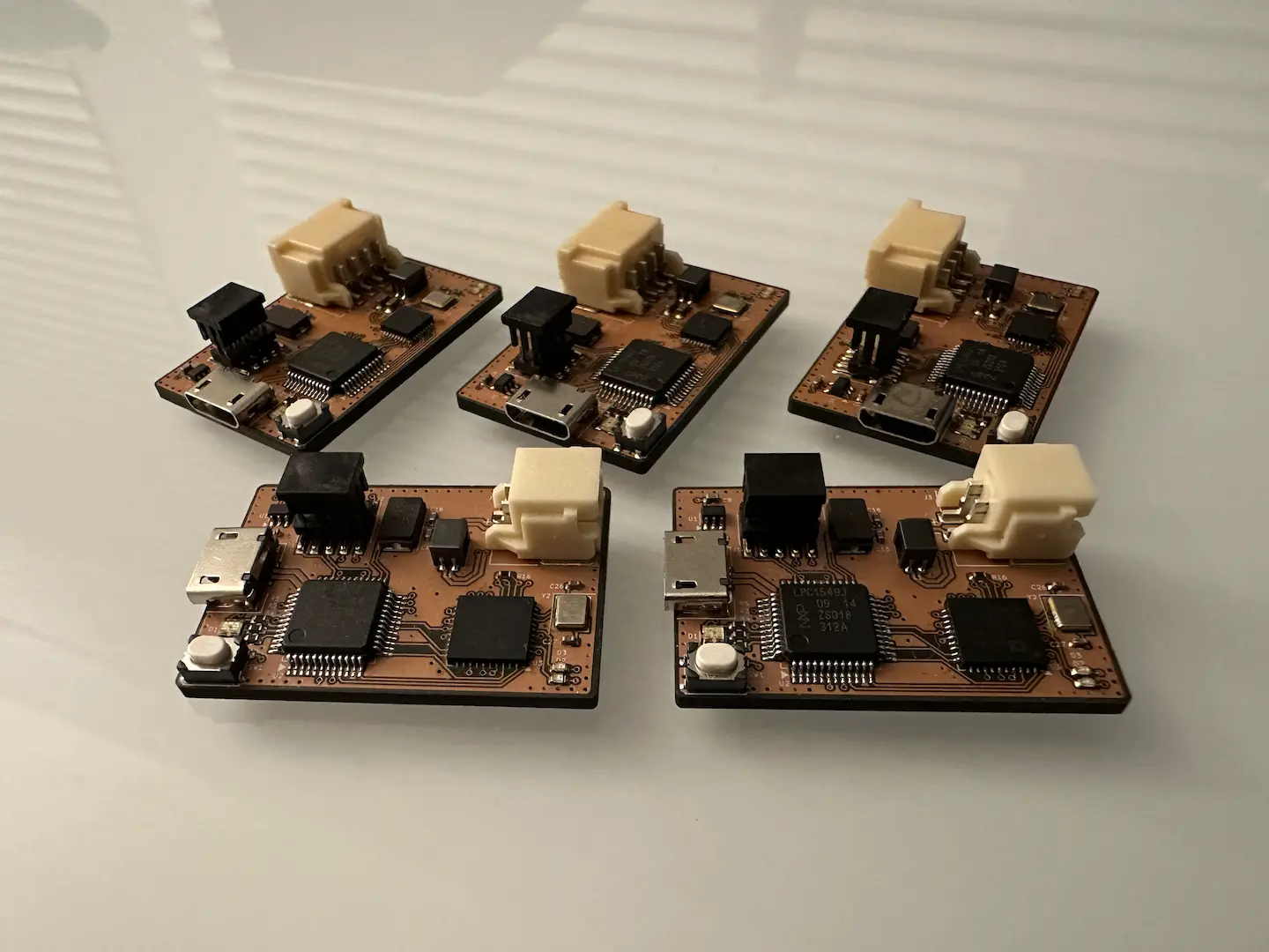
(Please excuse the lack of PCBA picture my phone’s camera broke at the most inopportune time.)
Inspired by my housemate’s constant asking of me to do things for them, I decided to build an ultra low-power remote using parts I had on hand. To reduce the need to walk or strain one’s voice, it includes live microphone streaming. I am yet to be encouraged into making the speaker receiver, but the hard part is done.
Design
This design marked quite a few firsts. First is the low quiescent draw which at 2.5uA meant a charged battery can last literally years not counting natural depletion. I achieved this by locking everything except the microcontroller, resistor divider, and battery charger behind voltage regulators that I could turn off. I could’ve probably added FETs to switch the resistor divider and battery charger, but the gains would’ve been marginal at best. Second is the electret microphone amplifier which I sized with empirical measurements. The main issue was the HPF so that the DC bias doesn’t get amplified which I initially sized with a 10uF cap. This added a 3 second wake time so I later changed it to 1uF with only marginal sacrifice in audio quality (for my voice at least). Third is my first 1.8V device (LSM303AH) along with the appropriate voltage shifters. Last but not least, this was my first RF design. Wanting to maximize success, I did use Nordic’s recommended circuit and TI’s 2.4GHz PCB antenna.
While the digital layout was quite simple, the RF layout was interesting to say the least since I’ve never done it before. While optimizing heavily for board size, I made sure to keep the RF and digital circuits separate. A ring of vias surrounds the RF section to shield it from the digital section as well as providing a solid continuous RF ground. For traces that require controlled impedance, I made sure to add many ground vias surrounding them for shielding as well as maintaining that impedance. At the end of the day, all of my traces were so short it probably didn’t matter too much. The main mistake I made was routing the RF power trace underneath the microphone amplifier which produced audible but weak noise at the transmit rate.
Firmware
Getting the firmware working provided a slight challenge. Running on an ATtiny1616, I didn’t even consider encryption (although looking back it may be barely possible with the right sacrifices). Microchip Studio was the first of my worries with the MCC Classic code generator UI being difficult to work with and even having a bug in the generated code. Thankfully, I had enough knowledge of AVR to figure out the issue.
Next was transmitting the audio samples in real time since doing the SPI transfer for a packet wouldn’t fit in between two samples especially with packet overhead. I eventually settled on collecting 22 samples to be transmitted every 1ms in one larger packet. Since samples would be collected in an interrupt, I made sure to use two packet buffers to ping-pong between so that one packet would be written to while the other transmitted.
Last was the sleep mode where I had to figure out why the quiescent current was so high (~130uA). I desoldered just about every part until I narrowed it down to the resistor divider. Since the current passing through 2MΩ @ 4.2V is quite small, it had to be the microcontroller. As it turns out, holding a microcontroller’s IO mid-rail even when it’s an input increases quiescent draw significantly. Since I still wanted to monitor the battery voltage, I enabled the pull-up before sleep to hold the pin near the battery voltage and finally got the quiescent draw down to a sweet 2.5uA.
Overall, this project was a resounding success. Definitely a few things to improve on for future projects, but I’m quite proud of it.

Comments