Baremetal C/C++ on CH32V (including FreeRTOS and TinyUSB)
https://github.com/dragonlock2/miscboards/tree/main/wch
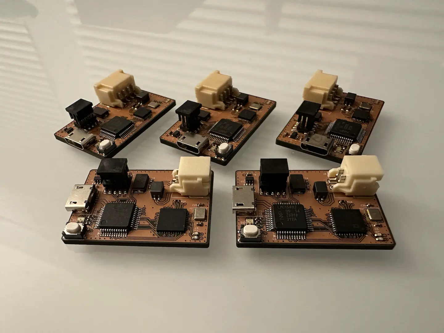
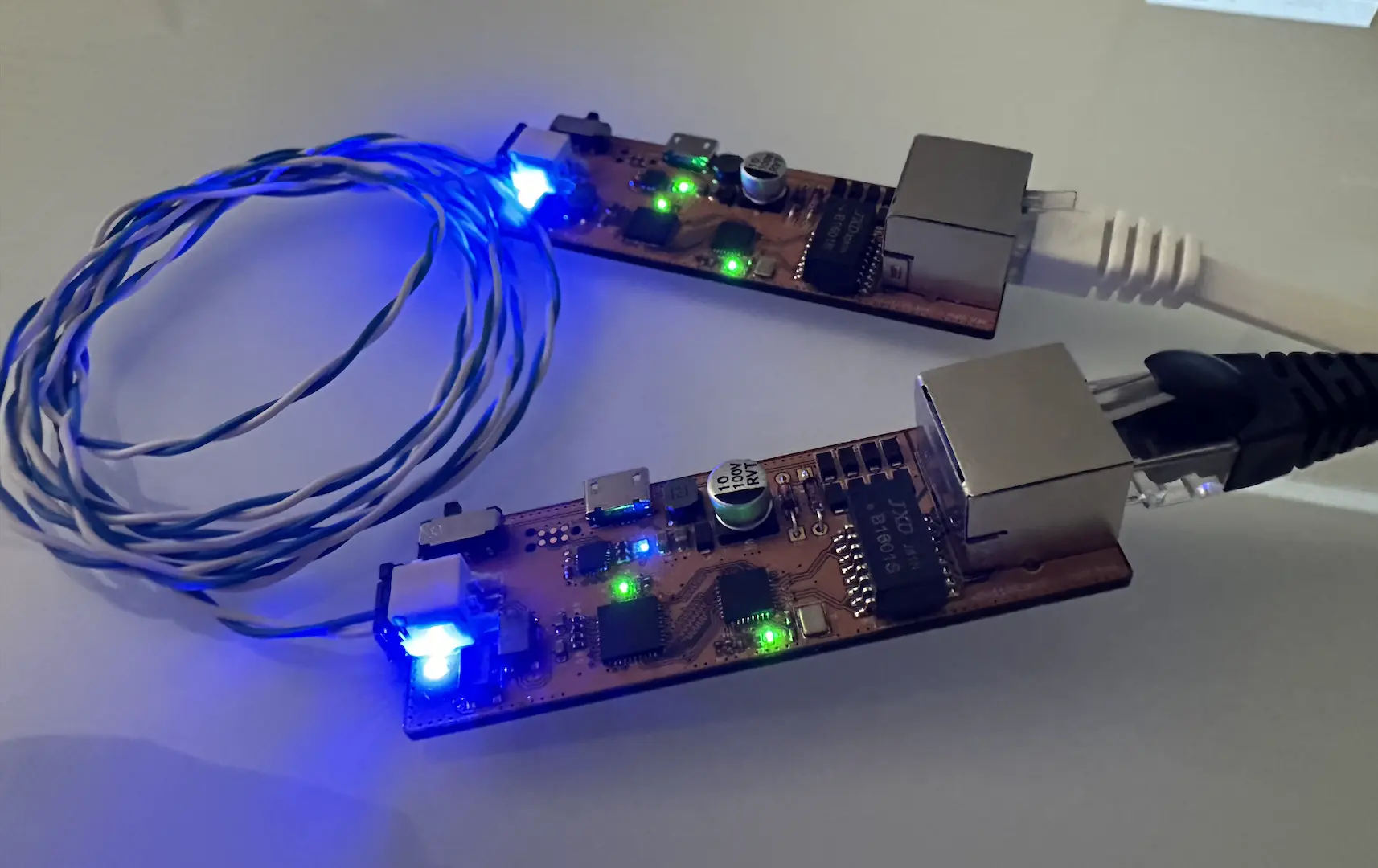
I’m a little late to the party, but I recently bought a bunch of CH32V003 and CH32V203. Unlike other Chinese chips, these ones are easily acquireable so I can actually use them in projects. With it’s bare minimum set of features (UART, SPI, I2C, ADC) and low cost, the CH32V003 is a worthy alternative to low-end AVR. By adding USB, CAN, and a more powerful core, the CH32V203 replaces a lot of mid-range ARM chips. There are more chips in WCH’s lineup with even more interesting features, but these are the ones I’m starting with.
Instead of using MounRiver Studio IDE or even the entirety of the vendor SDK, I decided to build a toolchain myself. First was the compiler. I initially tried compiling LLVM and GCC from source, but ran into issues bootstrapping libc. I eventually gave up on LLVM since it doesn’t yet have RV32E support in mainline. I ended up using riscv-collab/riscv-gnu-toolchain which has scripts to streamline building up a toolchain. Next was OpenOCD, which I had to request the source code of from WCH since no one had done so recently and I needed WCH-LinkE suppport. After realizing some of my WCH-LinkE came unflashed and then flashing WCH’s provided bootloader and app binaries, I had a set of working debuggers.
From here, I put together a set of CMake scripts to ease the build process and bringup of new projects. I won’t go into too much detail on the CMake front since there’s better tutorials out there and my source code is available. Instead, I’ll go over the more interesting parts. The process for CH32V003 and CH32V203 are more or less exactly the same.
linker script
The linker scripts provided by the vendor SDK were quite bloated, hard to read, and contained a lot of legacy parts. They appeared to be copied straight out of SiFive’s examples. Wanting more control and a learning experience, I wrote my own. After specifying the ROM (flash) and RAM regions, these are the crucial sections to get C working.
.text- This is where all of your functions get placed by default. I also put.rodatahere which refers to read-only constants, but some people do split it off into a separate section. Notably, I placedreset_handlerat the very beginning of ROM, which I’ll go into more detail later..data- Variables that have an initial value live here. Importantly, the initial values live in ROM and must be copied into RAM by the startup code. I also put the value of__global_pointerhere, offset 2048 bytes from the start of RAM, to allow linker relaxation..bss- Variables that are zero-initialized live here. Since the hardware doesn’t do it, our startup code will zero out this section on boot.
Importantly, we also define a couple of symbols (_data, _edata, _data_rom, _bss, _ebss) that our startup code will use to setup .data and .bss. _end and end get used by the default implementation of sbrk to provide a heap. While I’ve seen many people allocate a stack section, I simply have a marker for the top of stack _eram and acknowledge that any RAM remaining after .data and .bss are allocated become my heap and stack.
If you’re using C functions or C++ constructors that run before main(), you’ll need to add the following sections.
.preinit_array- This is an array of function pointers that run before things ininit_arraydo..init_array- This is an array of function pointers that run beforemain()..fini_array- This is an array of function pointers that run aftermain()returns. Sincemain()rarely returns, we can consider this optional but I left it in to be complete.
It took several hours of debugging to get C++ exceptions working, especially with such poor documentation from the internet and ChatGPT. Eventually, I realized it boiled down to adding the following sections (to ROM). Funnily enough, this even works with Newlib-nano which is supposed to lack exception support by default.
.gcc_except_table.eh_frame
startup code
As is my style, I opted to write the startup code in C instead of pure assembly. Here we define reset_handler, which we placed at 0x0 in the linker script. From the reference manual, CH32V starts executing instructions from 0x0 at boot. Since the interrupt vector table also lives at 0x0, this is typically a jump instruction to the reset_handler. However since I intended on relocating the vector table, I just let reset_handler occupy 0x0. Notably, we mark reset_handler as naked since we don’t need to save any registers as no one else calls it and also with O1 optimization to prevent inlining that was causing things to write to the top of stack.
In the reset_handler, we start by setting up gp and sp as this chip doesn’t do that for us. Then we can call memcpy and memset to setup the .data and .bss sections. Next, we modify a couple of CSR registers, one of which I haven’t a clue what it does since it’s undocumented. Notably, this is where we enable interrupts and interrupt nesting. We also setup the vector table here which I placed in RAM for flexibility. After that, we call libc_init_array() to run functions in .preinit_array and .init_array, then main(), and finally libc_fini_array(). We end everything with a while (1); to prevent further execution.
As an aside, my decision to relocate the vector table to RAM does invite discussion. Most applications won’t need the flexibility and would be better served having it in ROM. If needed, I’ll probably add a compile flag in the future to enable a constant user-provided vector table. The need to relocate at all I would say is useful if a bootloader that requires interrupts ends up being used.
drivers
Register definitions for each of the peripherals are the one place where I’ll almost always use the vendor provided ones. Those things can be quite a pain to write from scratch and easy to mess up on. I’ve written many drivers from just the register definitions, but in this case WCH provides a decent set of them in their vendor SDK which I reused.
I did end up writing the clock setup functions myself since the vendor SDK ones appeared to assume starting from boot. Since I wanted to eventually work on bootloaders which might use a different clock configuration, I wrote my own clock setup functions which made no assumptions about the prior config. Basically, we enable the internal oscillator and slow down the flash access before switching to it. From there we have a known good config to proceed from.
FreeRTOS
Since CH32V appears to have a pretty nonstandard RISC-V implementation due to it essentially being an ARM microcontroller with the CPU swapped out, I decided against adding Zephyr support for now. Instead, I decided to get FreeRTOS working. RISC-V support in FreeRTOS is pretty basic, with no support for interrupt nesting. It also uses a dedicated ISR stack (which is just the typical non-RTOS stack) to avoid tasks each needing enough stack space for interrupts. FreeRTOS also hooks into all of the interrupt handlers, at least those that need FreeRTOS, and calls an application-specified handler with the value of mcause. Since the FreeRTOS handler does register saving, I didn’t need an __attribute__((interrupt)) for my handlers and only needed to make the application-specified handler call functions from my original vector table.
While the initial port was easy, I kept running into a memory corruption bug with multiple tasks enabled. Even worse, the bug could take up to a minute to manifest. After many hours of debugging, I realized that ecall (used by portYIELD() similar to how ARM uses a PendSV) could preempt even if interrupts were disabled, so I used the software interrupt method WCH used in their SDK. Not liking this hacky way, I eventually realized that I had to modify the INTSYSCR CSR register to disable interrupt nesting. Just like that, I got mainline FreeRTOS working!
TinyUSB
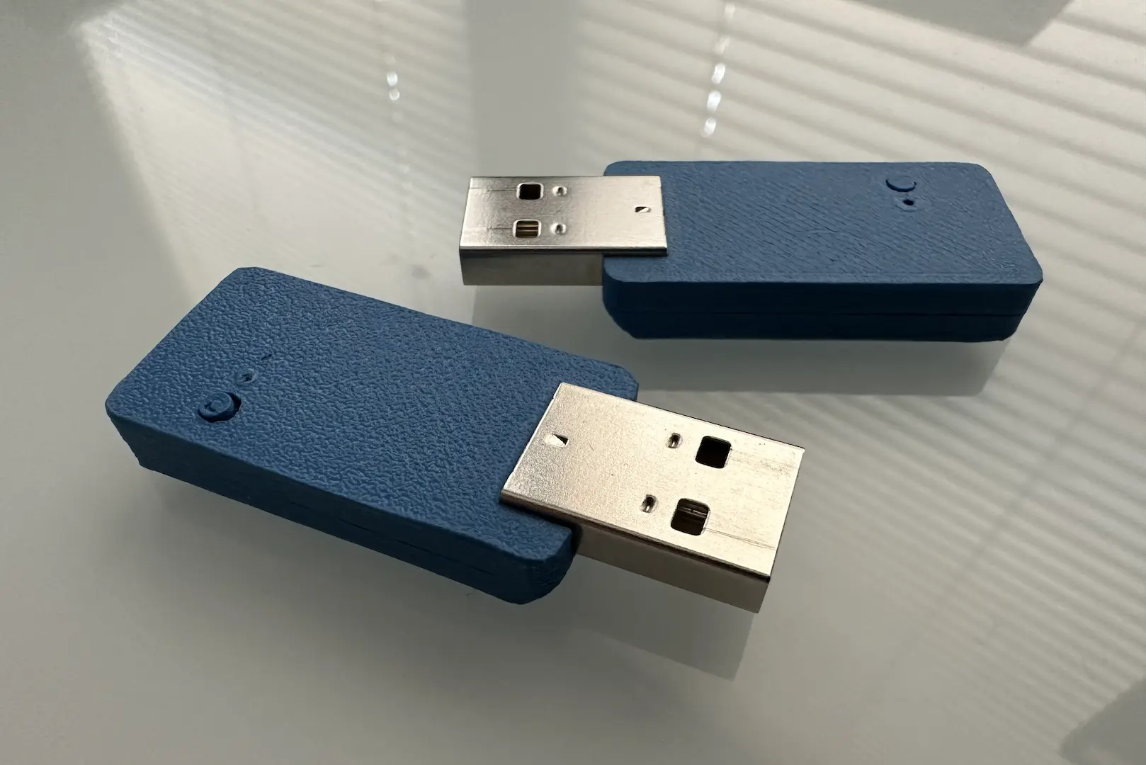
At a low level, USB is actually not so different from other commander-responder protocols like LIN. USB endpoints are essentially like LIN message IDs and can be written to or read from. The only difference in software is that since it’s so much faster and requires lower latency, DMA is more or less required. Packets need to be precomputed rather than done on the fly.
Due to how well-documented it is, adding TinyUSB support was pretty straightforward. I simply followed the porting guide. I drew a lot of inspiration from the CH32V307 USB HS driver, with a few notable differences. While the USB HS IP can specify a separate TX and RX buffer for DMA, the USB FS IP in the CH32V203 needs a combined 128-byte TX/RX buffer, with data placed in different halves. This necessitated allocating buffers in the driver instead of using application provided ones.
While working on audio streaming, I realized the USB HS driver doesn’t have isochronous endpoint support, so I added it to my USB FS driver. The only difference is not requiring an ACK from the host. It was at that point where I realized USB supports up to 1023-byte packets that are only used by isochronous transfers. Bulk transfers split things up into 64-byte packets. The reference manual and vendor SDK didn’t detail how the TX/RX buffer should be setup, so by guessing and checking I realized that it still assumed a 64-byte split which means received >64-byte OUT packets would overwrite queued IN data. A notable limitation, but not one that affects most applications.
conclusion
This project was a complete success! It was an excellent learning experience and I had to really dig into the implementation of exceptions in C++, task switching in FreeRTOS, and low-level USB implementation. Next, I’ll look into Zephyr, LLVM, and Rust support.


Comments