
Solder Dispenser
https://github.com/dragonlock2/miscboards/tree/main/wch/solder_dispenser https://github.com/dragonlock2/kicadboards/tree/main/projects/solder_dispenser
Prior to this project, the way I applied solder paste was by using tweezers to move tiny globs around. This worked well, but was tedious, slow, and inconsistent. For fine-pitch parts, I often just placed a line of paste across the pads and dealt with the bridging after. Solder stencils work but are rather expensive if they’re only used for one-off boards. Solder paste dispensers like the I-EXTRUDER are the perfect middle ground and can potentially be mounted to a CNC for automated paste dispensing. Every design I found online was some combination of too large, externally powered, difficult to manufacture, not ergonomic, and not aesthetic. Thus, I decided to design my own compact battery-powered version.
electrical
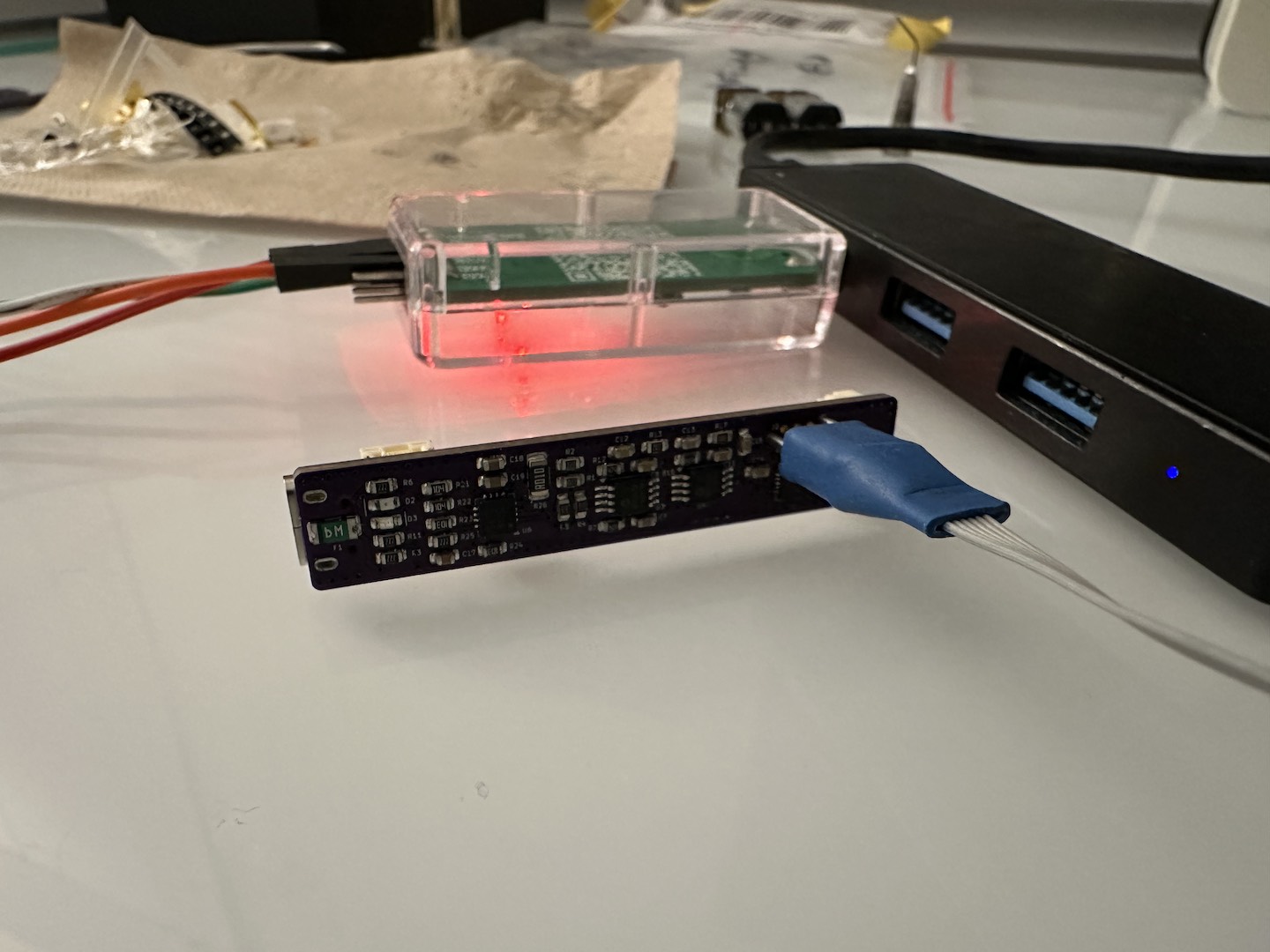
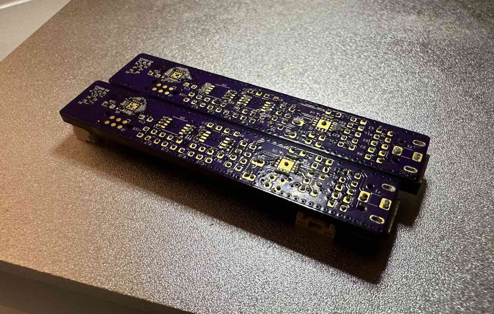
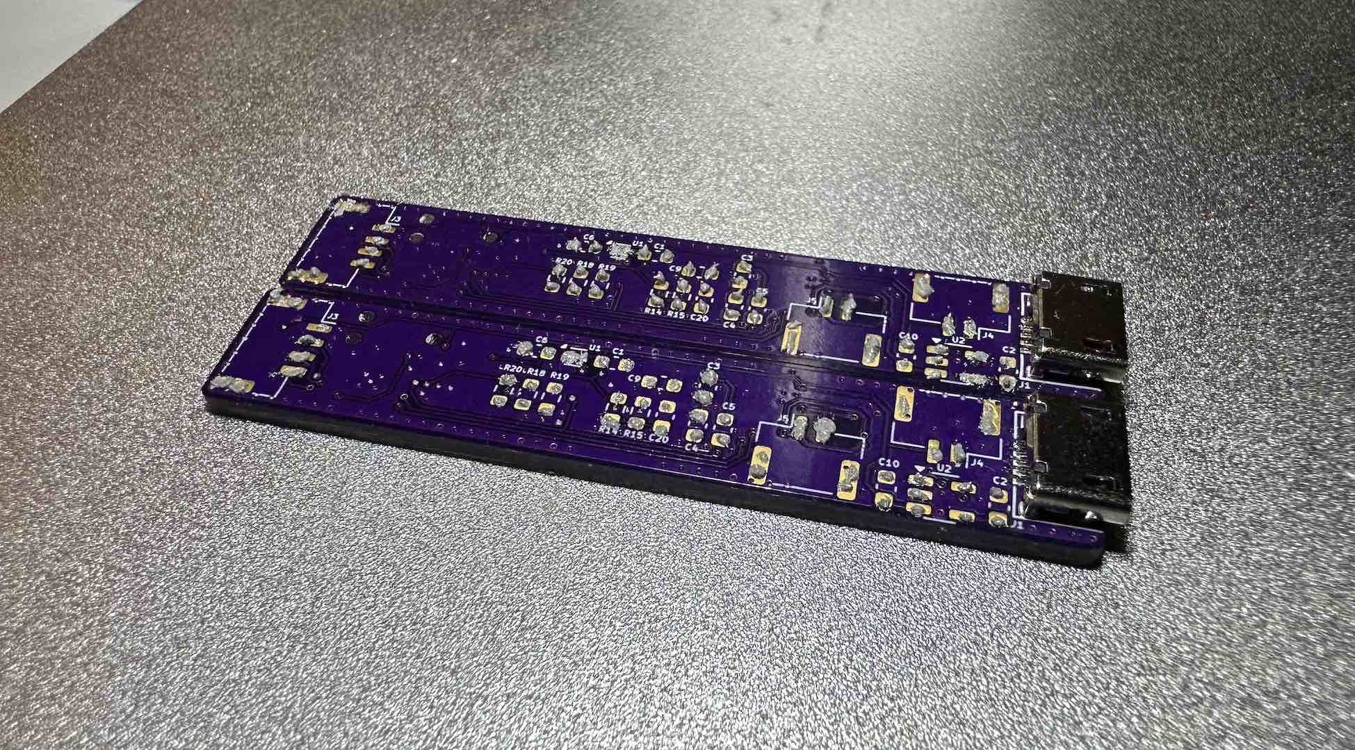
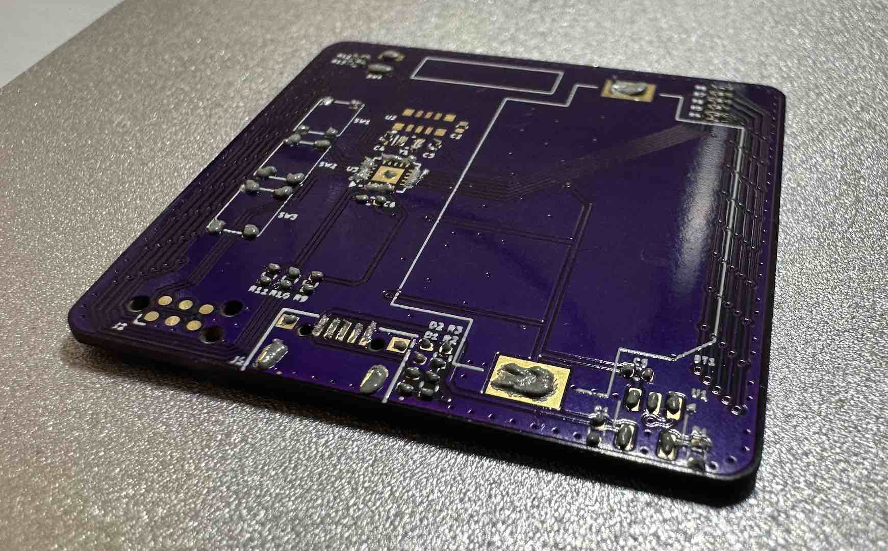
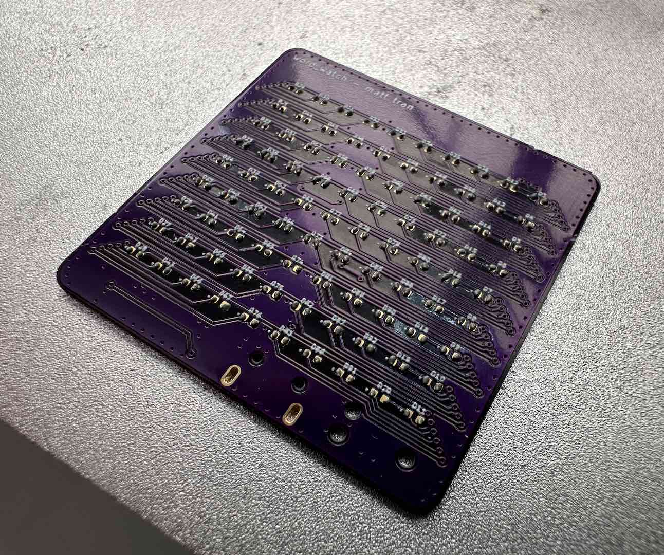
As always, the electrical design was relatively straightforward. Since this is a frequently used project with lower sleep current requirements, it was a good time to try out the CH32V003. This was also my first time using the STSPIN250 as a motor driver and not an audio amplifier. The layout wasn’t too bad, I fit it into 2 layers as usual.
The most interesting part of this circuit is the ripple counter which looks at current ripples caused by motor brush commutation to measure position. Both TI and Microchip have near identical reference designs. Wanting to use fewer parts, I ended up designing my own signal conditioning circuit using LTspice. I modeled the ripple current as a sine wave current source using actual motor measurements as the parameters. Since we need to amplify the ripple frequency while filtering out the PWM frequency and load current DC bias, we essentially need a bandpass filter. To not miss steps caused by sudden load changes, we need a sharp cutoff below the ripple frequency. In fact, this is so important that my cutoff frequency is right at the ripple frequency. In the end my filter design consisted of a differential RC filter piped into a differential bandpass amplifier, into an inverting bandpass amplifier, into an RC filter, into a comparator with hysteresis.
mechanical
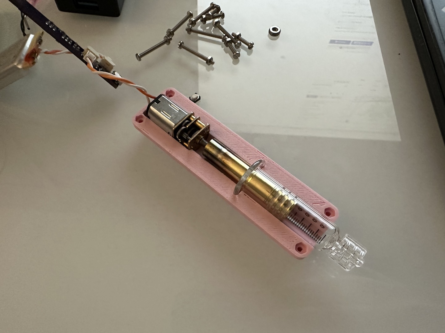
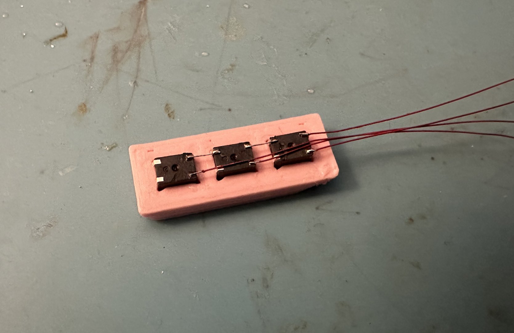
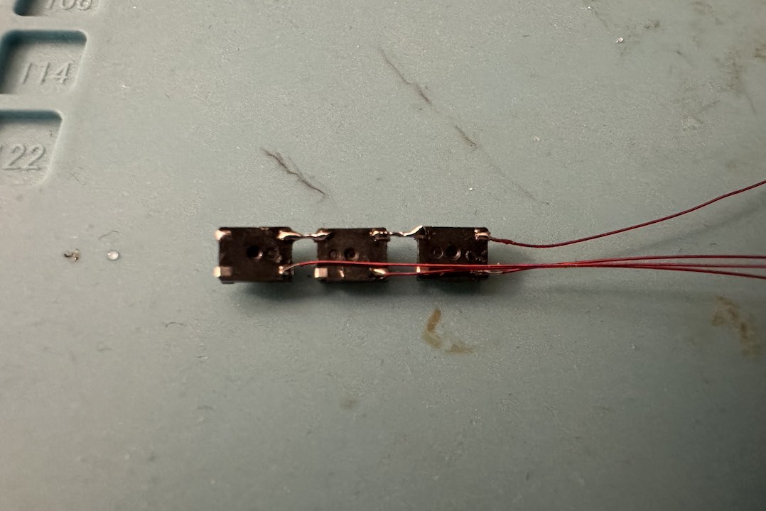
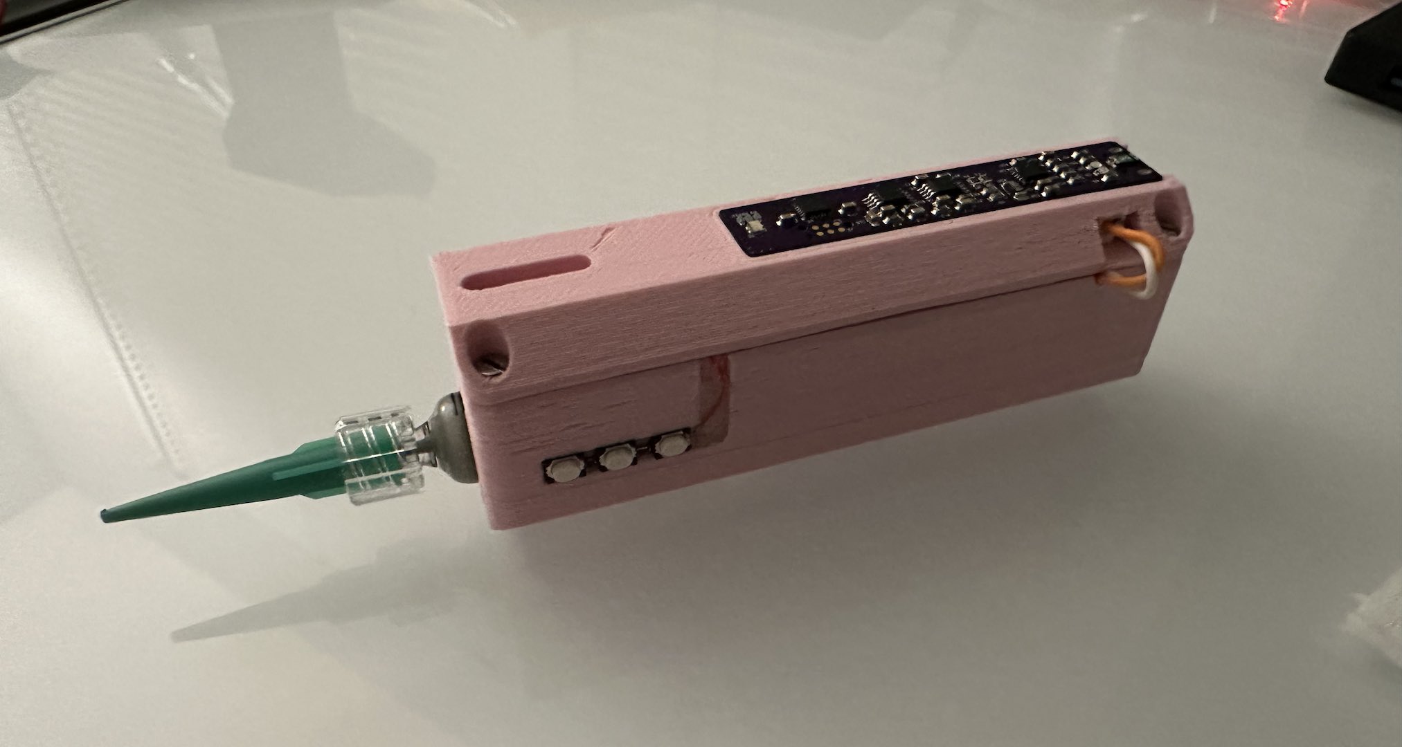
The key to keeping the device small is a good mechanical design. I went as small as I could with cheap, off-the-shelf parts. I got the high-torque geared motor with attached M3 lead screw off Aliexpress and the glass syringes off Amazon. Looking at the syringe plunger, I reasoned that it was a hollow pipe with caps held on with glue or pressed fit. After a trip to the gas stove, I was able to get the cap off to confirm. This allowed me to put the lead screw far further down the syringe, saving quite a bit of room. I was a bit lazier with the rest of the design as my switches mount was hard to assemble and the whole thing needs to be disassembled to refill. While the final design is thicker than desired since I only had larger batteries on hand, it’s still more compact than anything else I’ve seen.
firmware
Thanks to my prior work building an SDK for baremetal CH32V development, I was able to focus more on application development. The UI is simple and allows the user to select an amount to extrude as well as continuously extrude if needed. The ripple counter worked surprisingly well for closed-loop position control after realizing I needed a small delay when switching direction. I’m sure it’s still missing a step here and there, but it works well enough.
The hardest part was actually getting low-power sleep down to the advertised 9uA. The key was setting pullups on unused pins and disabling the ADC. I also needed to enable the SWIO as a wakeup pin to allow flashing while asleep, which interestingly also lowered current draw further. Importantly, the chip needs a full power cycle for sleep to work, otherwise it just stays awake. The 9uA also only applies to 3.3V as I saw it go as high as 26uA at 4.2V. Even more, I had one chip that drew far more sleep current, likely due to overheating while soldering. While the CH32V003 is certainly not perfect, for $0.10 a piece it has its place.
tuning
The most difficult part of this entire project was getting the paste to dispense even somewhat consistently. At one point I suspected my ripple counter being inaccurate and tested with water. To my surprise, it was quite precise so I continued trying.
For reference, I’m currently trying Chip Quik TS391SNL as my solder paste of choice. It’s room temperature stable and by keeping it in airtight containers, I hope it lasts longer than a year. To refill a syringe, I found that removing the plunger and injecting from there works best. When putting the plunger back, use a thin wire to break the airtight seal so you can remove the air that gets trapped between the plunger and paste. Since my paste is T4 type, down to a 25AWG needle works well. Make sure to use the plastic conical needles as the gentle ramp prevents clogging.
For dispensing a precise amount, my initial idea was to overextrude and then retract. Since solder paste is so viscous, I imagined that adding more pressure initially would get it to dispense faster. That idea was impossible to tune well as I kept getting extra paste oozing out after the initial dispense. Inspired by 3D printers and the I-EXTRUDER, I eventually found that the prime/retraction system works far better. It’s actually the same implementation as my initial idea, but with a different thought process. At rest, we relieve pressure on the paste by retracting a certain amount, preventing oozing. To dispense, we extrude the amount we want plus a prime amount equal to the retraction, then retract. The key to making this idea work was adding a continuous extrude option to the UI so I can prime the needle after a refill. Upon stopping the continuous extrude and retracting, the paste would be at the perfect position for dispensing tiny amounts afterwards. With that implemented, I was able to find a prime/retraction amount that worked well. It’s far from perfect and not as consistent as I’d like, but the end result is functional.

Comments