
Basic CH32V Zephyr Support
https://github.com/dragonlock2/zephyrboards https://github.com/dragonlock2/kicadboards/tree/main/breakouts/usb_pdmon
While stocking up on CH32V chips, the recently released CH32X035 caught my eye. It had USB PD support which I’ve wanted to play with for quite a while. Since Zephyr recently added a USB PD stack, I figured this was the perfect time to port Zephyr to CH32V. I thought it would be fun to get the USB stack ported too. What followed was a journey riddled with hours of debugging and much despair, ending with a 100% successful project.
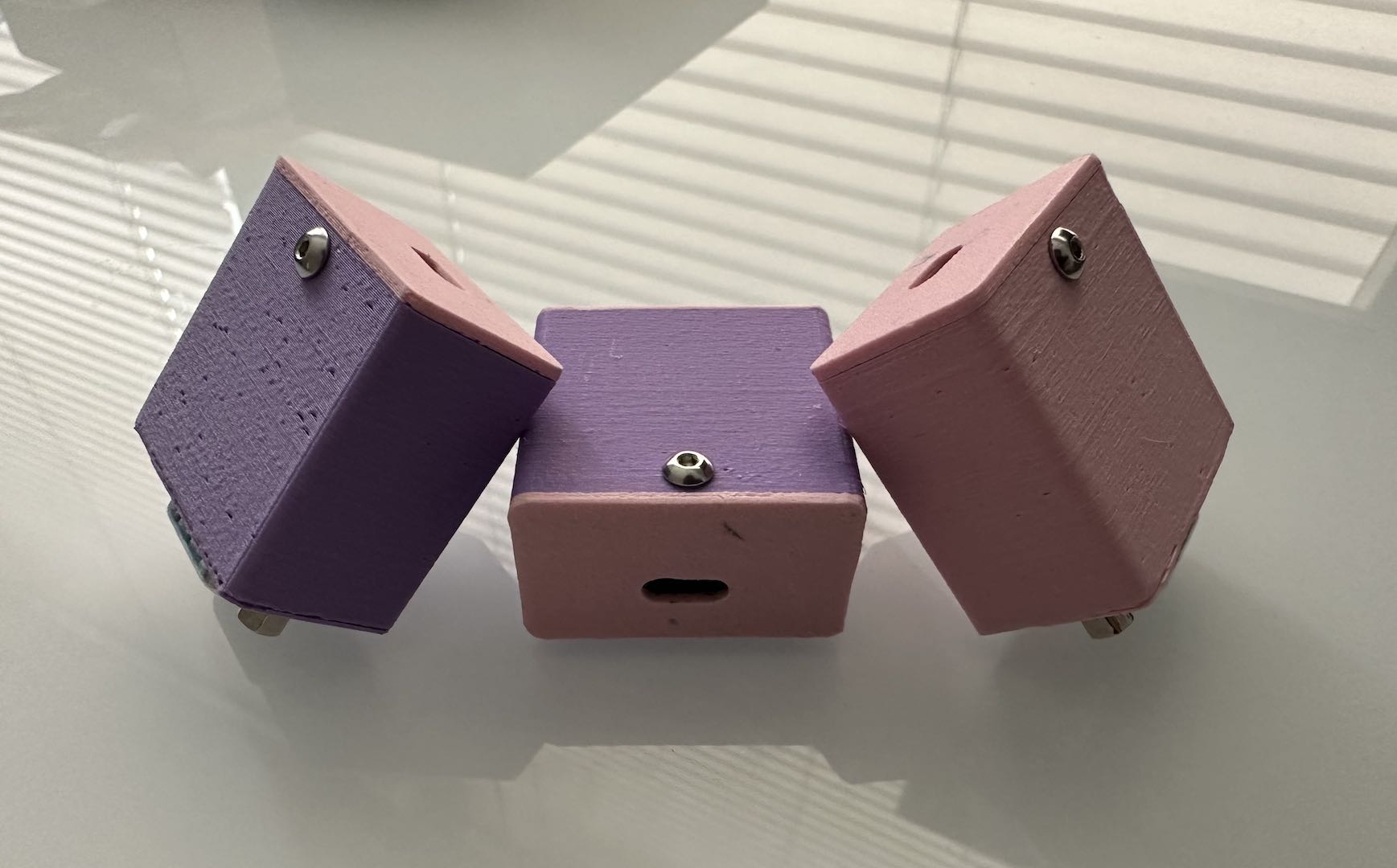
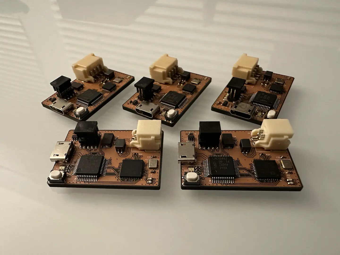
hardware (usb_pdmon)
Wanting to feel like I was saving money, I didn’t buy an eval board and instead designed one myself. As always, the process was quite straightforward. WCH’s documentation isn’t the best so I followed the eval board’s schematic and added the usual 5.1kΩ CC pulldowns and a button I correctly assumed would trigger the bootloader. While the oscillator isn’t technically accurate enough for crystal-less USB, it works so I’m not complaining. Since I lacked parts at home that go above 48V, I ended up spec’ing everything for 30V. I also added voltage and current monitoring.
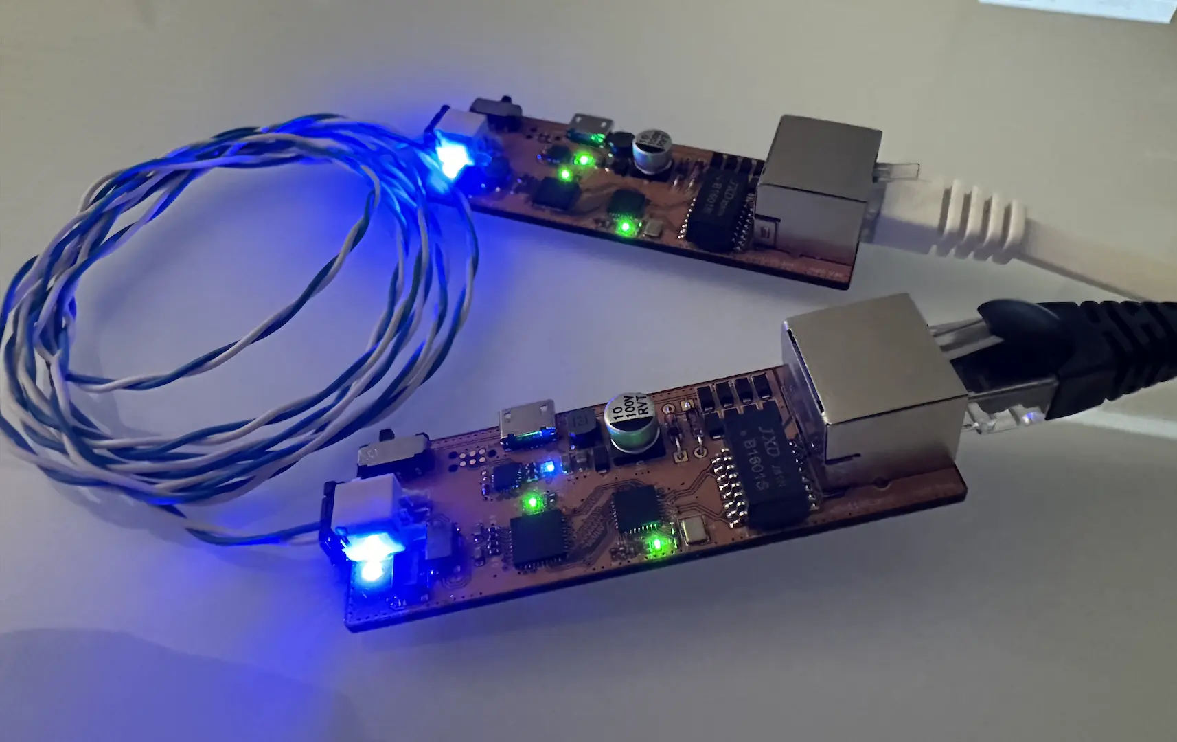
I also tried a new discrete LIN transceiver design to replace the half-failures from lpc845_lin. By using a voltage divider (with Zener clamp) instead of a diode-based level shifter, we can shift up the threshold for a low. It worked for vehicle length buses with multiple nodes, so I’d say this new design is a success. In case I wanted to apply external power, I added a bidirectional load switch using PMOS since this had to work up to 30V and I didn’t have the right boost drivers.
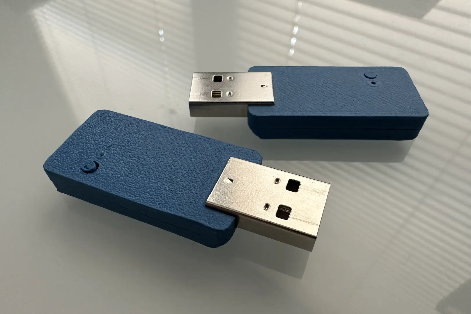
Since computers with higher voltage USB PD output are quite rare, I also designed a USB C splitter. With it, we can talk USB PD to one port and normal USB to the other. I forgot that USB cables only have one CC wire, so it only works in one orientation. To make this work passively, it would need to be a USB C male to female instead.
Zephyr support
The process for porting to Zephyr was more or less exactly the same as Basic LPC845 Zephyr Support. The API design and CPU core across all CH32V parts is very similar if not exactly alike, so moving to say a CH32V203 or CH32V307 should be quite easy.
RTOS
Since the approach to CH32V’s interrupt system isn’t spec-compliant, I ended up making a new wch_ch32 family for adding core SoC support. Specifically, it seems like WCH reused the ARM NVIC when creating the CH32V chips. Based on my knowledge of the CLIC, it doesn’t seem like RISC-V properly supports interrupt preemption as ISRs are entered with interrupts disabled. The NVIC can do proper preemption, but the Zephyr RISC-V support is not yet well set up for this and I didn’t want to maintain a branch. Either way, I ended up keeping things much simpler by using a single interrupt level.
I encountered two major problems while working on RTOS support, the first being interrupts weren’t triggering and the second being memory corruption on task switching. My long debugging sessions culminated in this giant comment documenting my workarounds, which I’ll summarize here. The normal RISC-V interrupt behavior is that interrupts are simply disabled upon entering an ISR and must be manually re-enabled. Zephyr uses this behavior for task switching, relying on the next thread to re-enable interrupts as needed by writing to mstatus. Unfortunately, CH32V also needs an mret to exit the interrupted state so I had to hack that in before task switching. Notably, this also re-enables interrupts unless one clears MPIE first upon calling the IRQ handler before jumping to Zephyr’s handler. It’s a real good thing I learned RISC-V assembly in school.
The resulting support is definitely hacky and might need updating with future Zephyr updates, but it’s working great. For more proper support, I still need to factor out the timer, clock, interrupt, and pin control drivers, but I’ll probably never get to those.
ADC
Adding an ADC driver was a good first thing to work on. It also helped me fully understand the Zephyr ADC API. It’s actually pretty smart and flexible, allowing both a recurring scheduled scan, single scans, and anything in between.
The CH32V ADC is an interesting one to configure. It offers a fixed number of “rule” channels that are essentially scheduled ADC reads of a specific real channel with specific sample times. An ADC scan consists of sequentially performing all of the “rule” channels’ requests. Since there’s only one data register, a DMA is required to pull data off without losing any. Since I was running into issues with the source impedance being too high for the low sample time, I added support for lumping multiple rule channels together to increase sample time.
USB
I was able to pull most of my TinyUSB USB OTG/FS driver into Zephyr. Notably, the IP used in the CH32X035 is USB FS rather than the USB OTG/FS used in the CH32V203. They’re subtly different enough to require a different driver. Since the reference manual isn’t complete, it was a very good thing I had functional example code from the SDK that filled the gaps.
The initial USB driver support was relatively easy after fixing a couple bugs with the DATA0/1 toggling. Fixing the RTOS memory corruption bug exposed by this driver was a lot more difficult. Zephyr’s approach to USB drivers is slightly better than TinyUSB in that larger transfers are done with the Zephyr USB stack rather than the low-level driver itself.
After testing across all of my personal computers, I tried it on my work laptop. To my dismay, it didn’t work. It also didn’t work on my friend’s computer. The WinUSB driver from Windows was failing to initialize. One of the early things I ruled out was the Zephyr USB stack by updating another one of my projects to it. After much debugging using Zephyr’s amazing logging subsystem, I realized that I was getting a TX done interrupt before I queued the next packet for sending. I then realized that this issue would only show up after I stalled an endpoint. The issue was that Windows was checking for a response too soon after sending a setup request and subsequently reading a stall. When it proceeds to try again with another setup request, it ends up reading the response from the prior setup request! This meant that my driver wasn’t clearing the stall fast enough which I fixed by doing it in the RX interrupt. In a way, my initial assumption that it was a latency issue was correct.
Another issue showed up when trying to attach my USB device to WSL, which again didn’t work on my work laptop. Turns out I had a typo in my prior fix, which you won’t see in the git history because I force pushed and erased it.
USB PD
At a low level, USB PD is just a half-duplex protocol occurring over the one CC line, along with some out-of-band signaling using the DC voltage levels. To implement the API Zephyr needs, we mainly need to set CC pull resistors, read what voltage bounds the CC pins lie in, and send/receive USB PD packets. Importantly, we must automatically send a “GoodCRC” back to any messages that require it. With all that implemented, I got the examples working.
Issues arose when I tried sending a “GetSourceCaps” to negotiate a new voltage/current level. I simply could not get it working, with the power source frequently cycling power and strange program hangs and hard faults. I thought debugging memory corruption was hard, but trying to debug with power cycles imminent was even harder. Even attaching a debugger would somehow cause a full reboot.
Confident it wasn’t an RTOS issue, I dug all the way down the stack and ended up writing my own. USB PD power negotiation is actually quite simple. The source sends its capabilities (“caps”), the sink sends a request, and the source sends accept/reject and power supply ready as needed. To request a new power level, the sink sends a “GetSourceCaps” message to start the process over again. One may wonder how collisions are handled. In PD 2.x, there isn’t a clear way. In PD 3.x, the CC DC voltage set by the source identifies who can transmit. I haven’t dug into it, but that’s probably the issue with Zephyr’s stack because I got power cycles when not obeying the PD 3.x flow control rule. At the end of the day, everything worked!

Comments