
Word Watch
miscboards/microchip/avr/word_watch
kicadboards/projects/word_watch
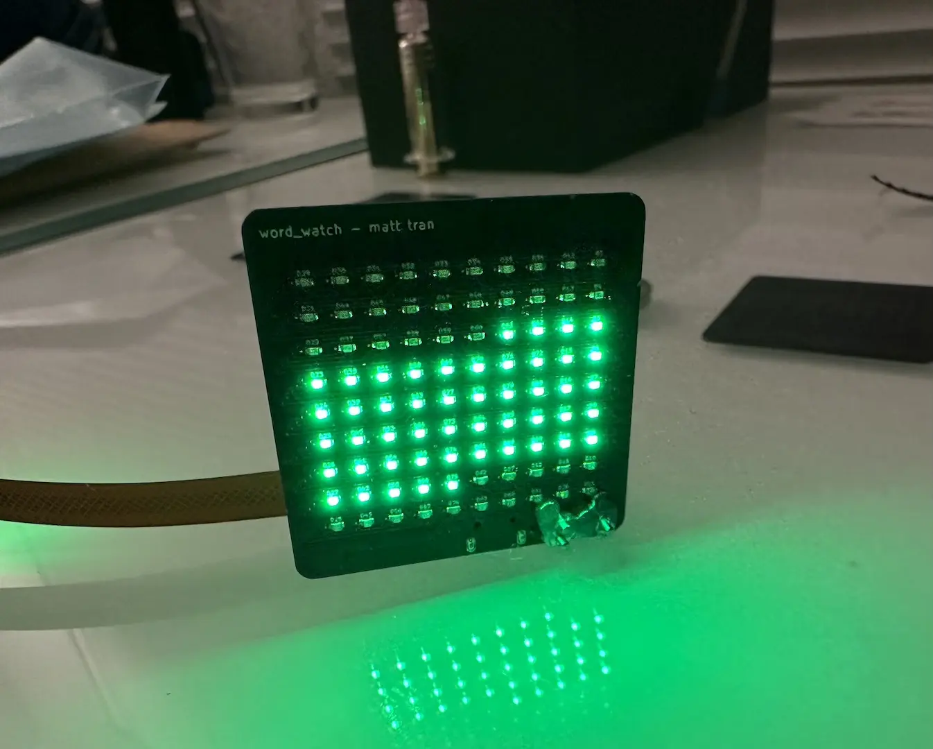
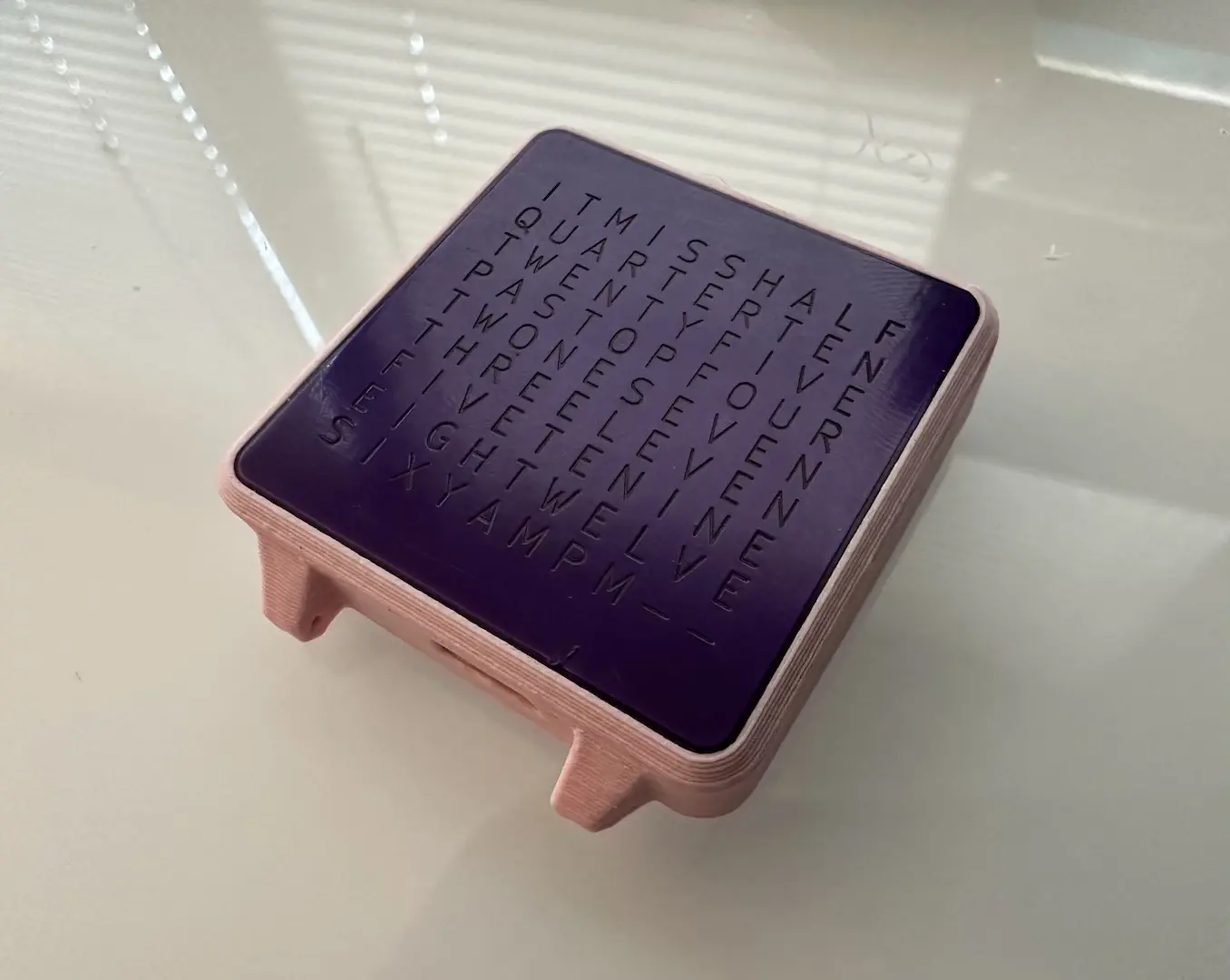
After seeing those word clocks, I wanted to make my own. If it isn’t obvious, I love making things smaller so of course I had to build a watch version. Turns out, that’s already been done. All of the English ones were too large, so I started by designing my own letter matrix. It’s an interesting puzzle, figuring out how to combine words to reduce size. I ended up fitting the necessary words in a 9x10 matrix. I also added a minute counter with two dashes, but didn’t realize that meant mapping 5 states into 4.
IT_IS_HALF
QUARTERTEN
TWENTYFIVE
PASTO_FOUR
TWONESEVEN
THREELEVEN
FIVETENINE
EIGHTWELVE
SIX_AMPM--
electrical
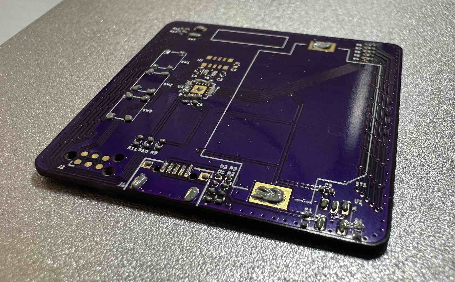
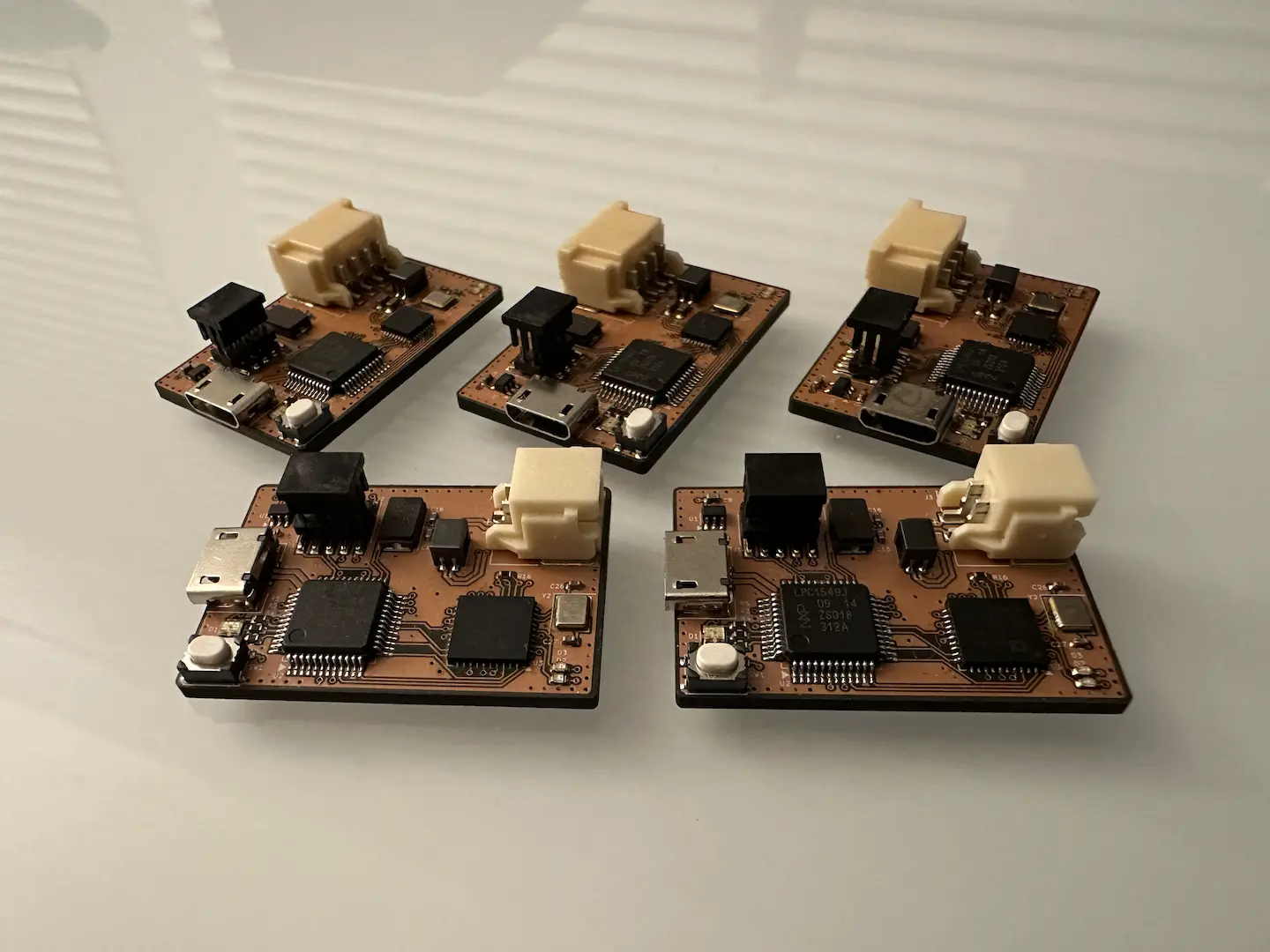
The electrical design presented a fun set of challenges, the first of which being minimal sleep current. For accuracy, I had to use an external crystal (~1min/month) or TCXO (~1min/year) which necessitates extra power draw. To my pleasant surprise it only adds ~0.5-1.0uA when used with an ATtiny1616 which meant this project was very possible with parts I had on hand. Unlike my nRF24 remote, this time I realized that I could measure battery voltage by comparing to the internal VREF, further lowering sleep current. During firmware development, I realized that my LED matrix was acting like a solar panel, driving the IO voltage mid-rail (increasing sleep current) so I had to drive them to ground in sleep. One unfortunate thing is that the ATtiny RTC peripheral can’t wake the chip slower than 1Hz which increases sleep current slightly. Overall, I was able to get an average ~3.0uA sleep current measured using my cheap multimeter which should result in a ~1.5year sleep battery life.
I initially wanted to use an accelerometer for shake-to-wake, but to save cost I used a vibration sensor. The SW-18010P was too sensitive and would wake with every slight movement. I went with the SW-18020P which needs a hard shake or tap to wake which I preferred for battery life.
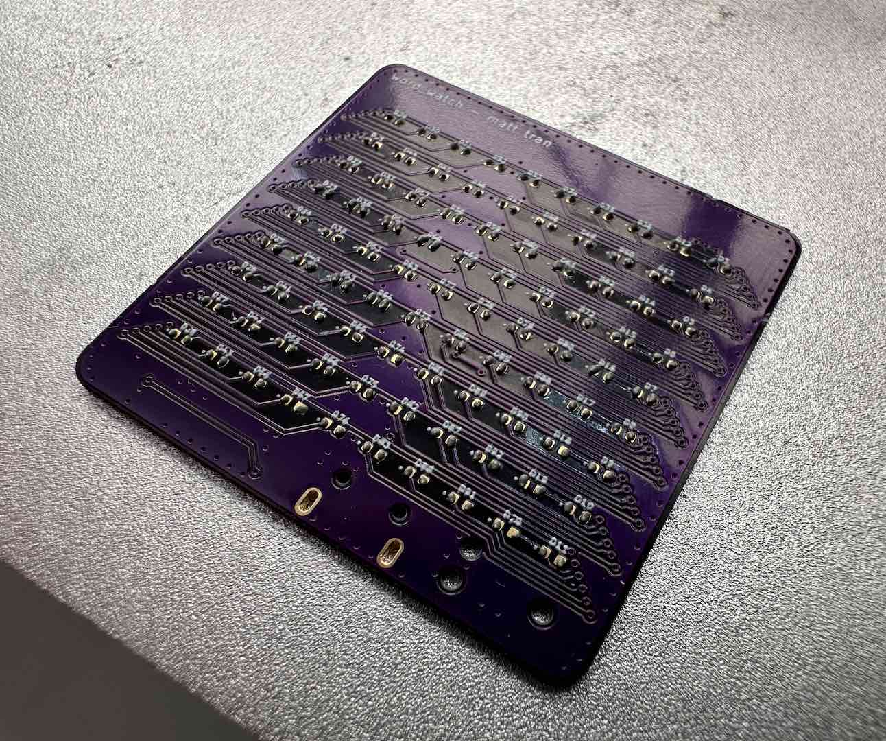
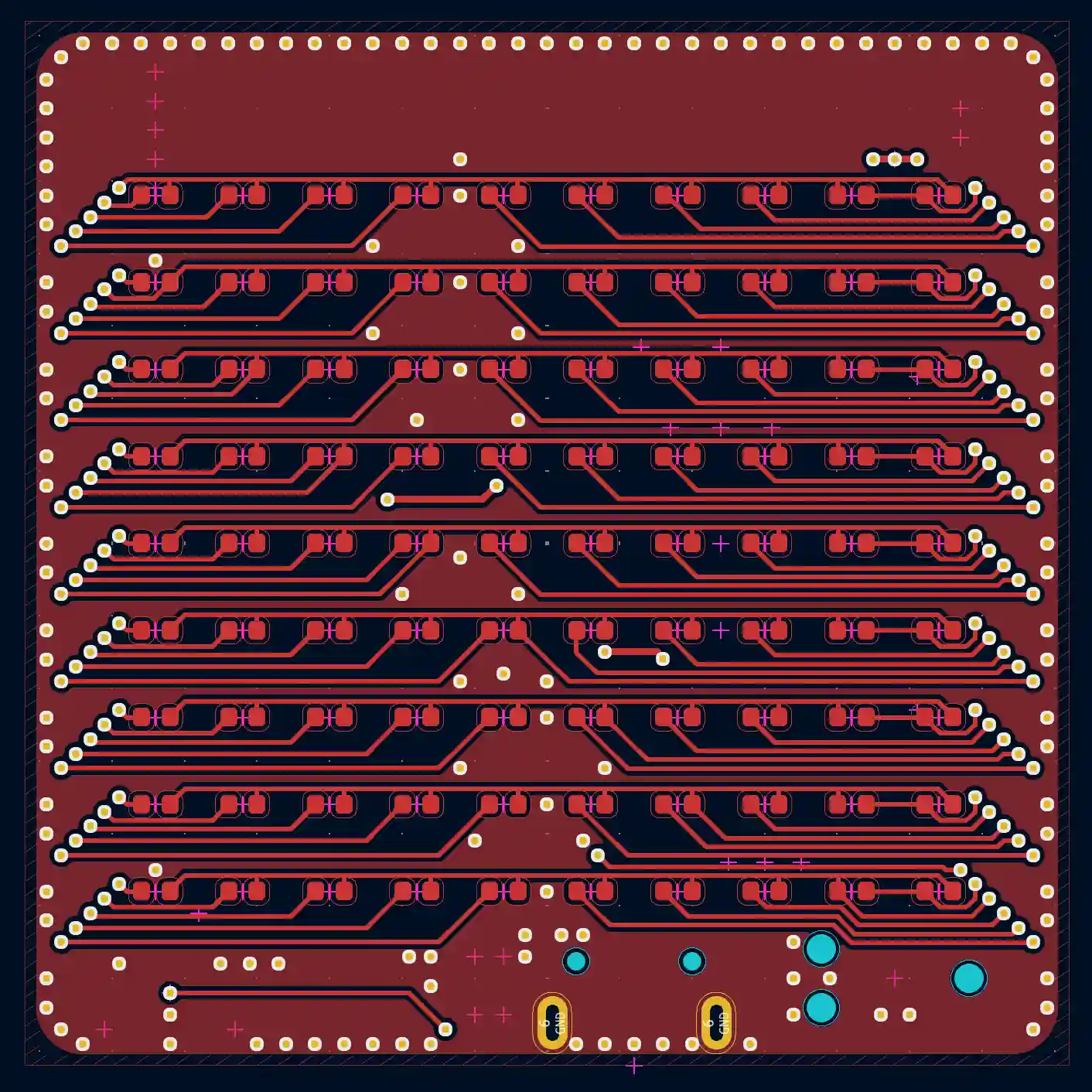
The other challenge was the LED matrix. I heard about Charlieplexing before and after looking into it realized what a genius idea it is. By using the tristate feature of regular GPIO, one can drive N(N-1) LEDs with N pins. An LED is selected by picking one pin to be positive and one pin to be negative. Notably, this means that only one LED can be on at a time in the worst case. Since it relies on the principal that a forward voltage applied across one LED won’t turn on 2+ series LEDs placed in parallel with the first, there are cases where lighting up one LED causes others to be dimly lit which I did witness on one board. Despite the disadvantages, using fewer pins was crucial so I went with it. I initially tried to organize the schematic like how the layout would be done, but later settled on the way the Arduino UNO R4 does it to minimize mistakes. The layout was where it got really interesting and I was heavily inspired by Willem Pennings’ design. Honestly, it’s hard to describe how to do the layout in words. I can best describe it as dedicating a row for each pin and the last column for the last pin. It’s easier if you just stare at it for a bit.
firmware
To speed up future firmware development, I started by creating a CMake SDK for ATtiny1616 similar to what I did for CH32V. Thankfully, support for the ATtiny1616 has improved since last year and I didn’t need all of my workarounds. The rest of the firmware wasn’t particularly difficult. There’s an eternal 1Hz interrupt which wakes the chip if needed and updates the time. If the wake reason is GPIO, we also enable the LED display for a bit before going back to sleep. The algorithm for knowing which letters to turn on is hardcoded, I couldn’t figure out a clean way of doing it. I kept the time changing simple, up to increment by a minute, down to decrement, hold to quickly change.
The most interesting part was the Charlieplexing driver, which uses a 120FPS*90LED=10.8kHz interrupt. At each step, we need to turn off all LEDs first before picking which pins are positive/negative. By only using PORTA and PORTB, I minimized the number of instructions this takes. To figure what to write to the PORT registers, I figured out an algorithm to generate a LUT for my layout. CMake runs this Python script to generate a header which then gets used in the driver.
mechanical
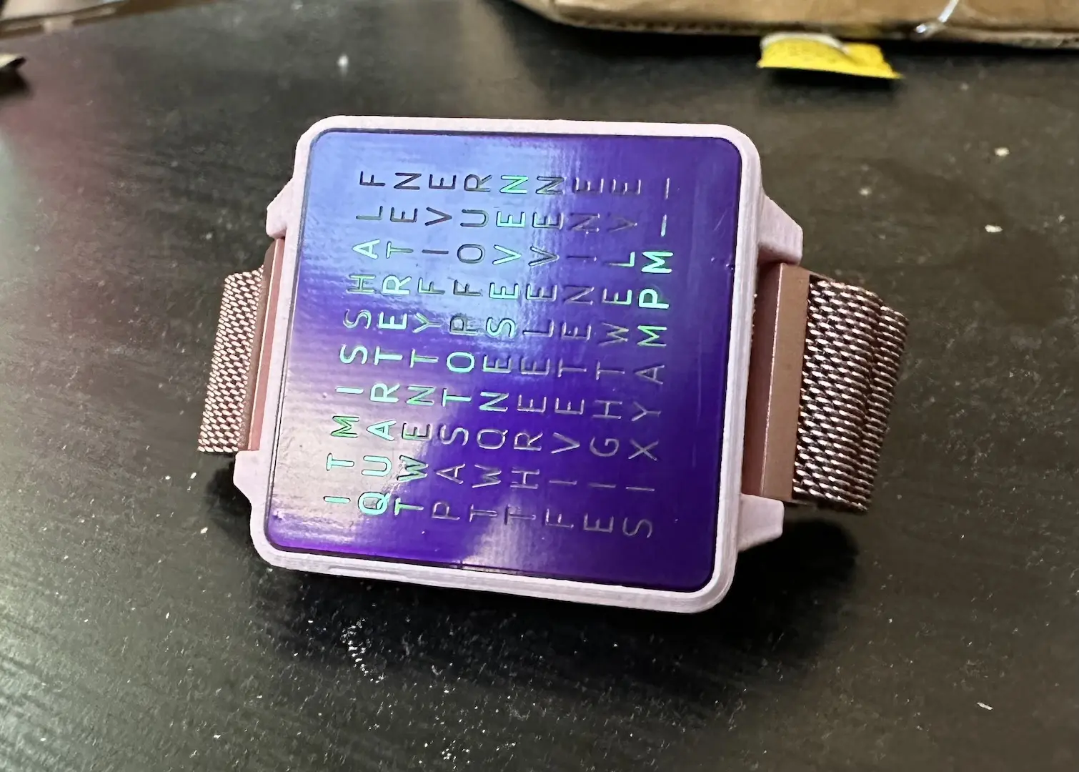
The hardest part in the mechanical design was the optics. Like Willem Pennings, I also had the idea to use a PCB to filter light for the letters. I used the dimensions he found to work well, but added a copper/soldermask layer to the back as well which he didn’t recommend. He was right, adding the second layer filtered out too much light and ruined visibility near sunlight so I had to sand that layer off. Unfortunately, that also increased light bleed between the letters. It’s a difficult compromise, but I had to settle for more crosstalk but better visibility in bright areas. If I had access to some of the technologies available at $DAYJOB, I could definitely do a better job but at greater cost.
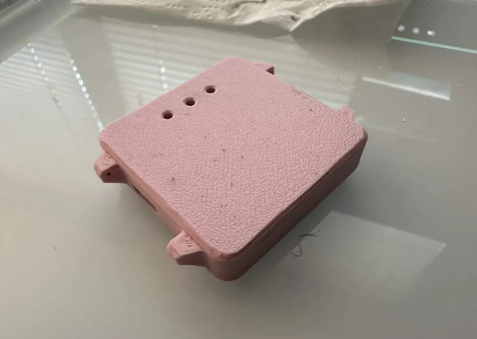
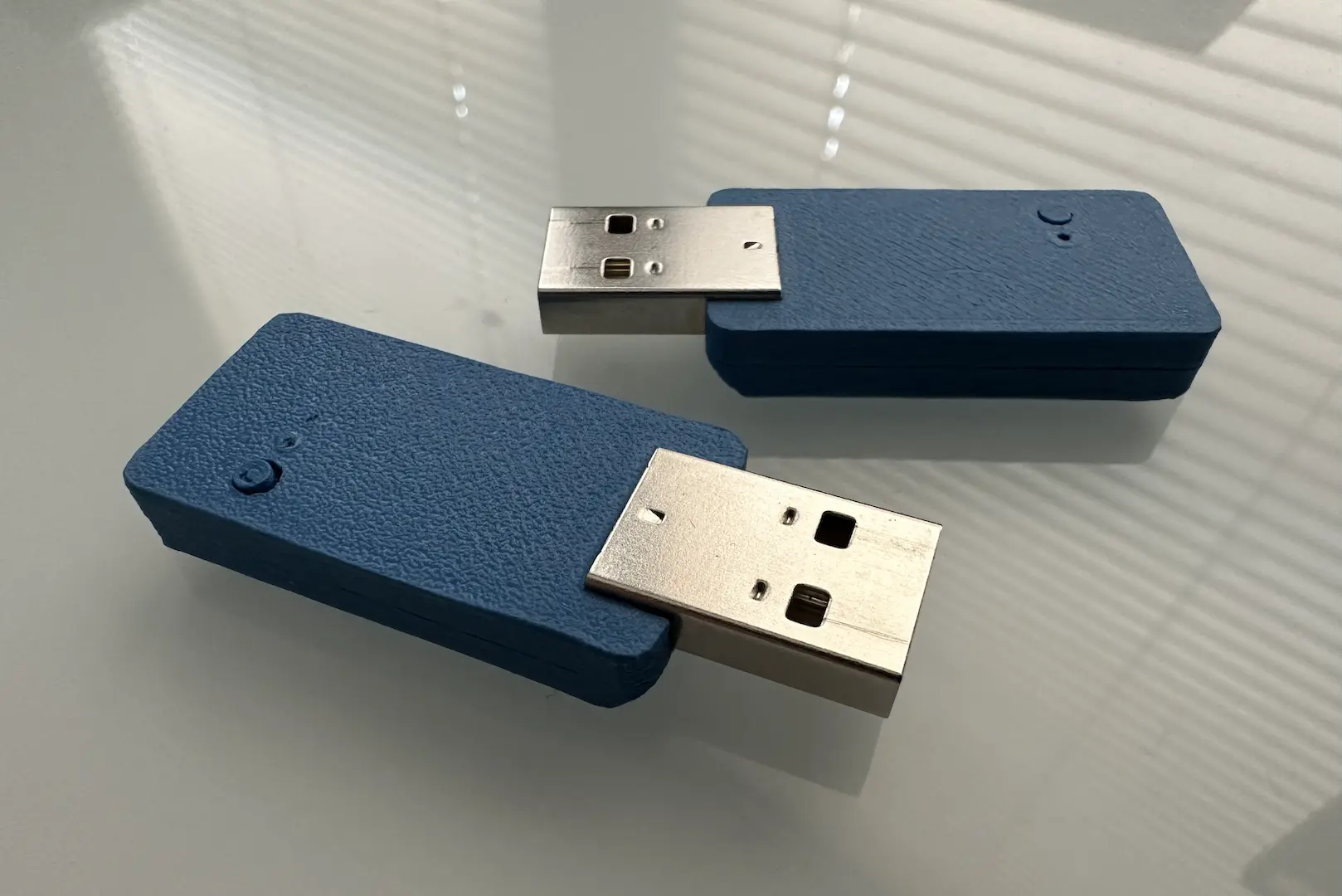
The rest of the housing design was relatively straightforward. To reduce light bleed there’s a plastic grid between the top and bottom PCB. I found a 0.4mm wall thickness to print well. I used 3 holes to access the buttons on the bottom since I was too lazy to design extenders. I would’ve used side facing buttons but didn’t have any. Waterproofing is quite difficult, I only thought about it for a bit. The bottom cover has a really nice snap fit. It fits a 20mm standard watch band. The top PCB was initially friction fit, but I later glued it for durability.
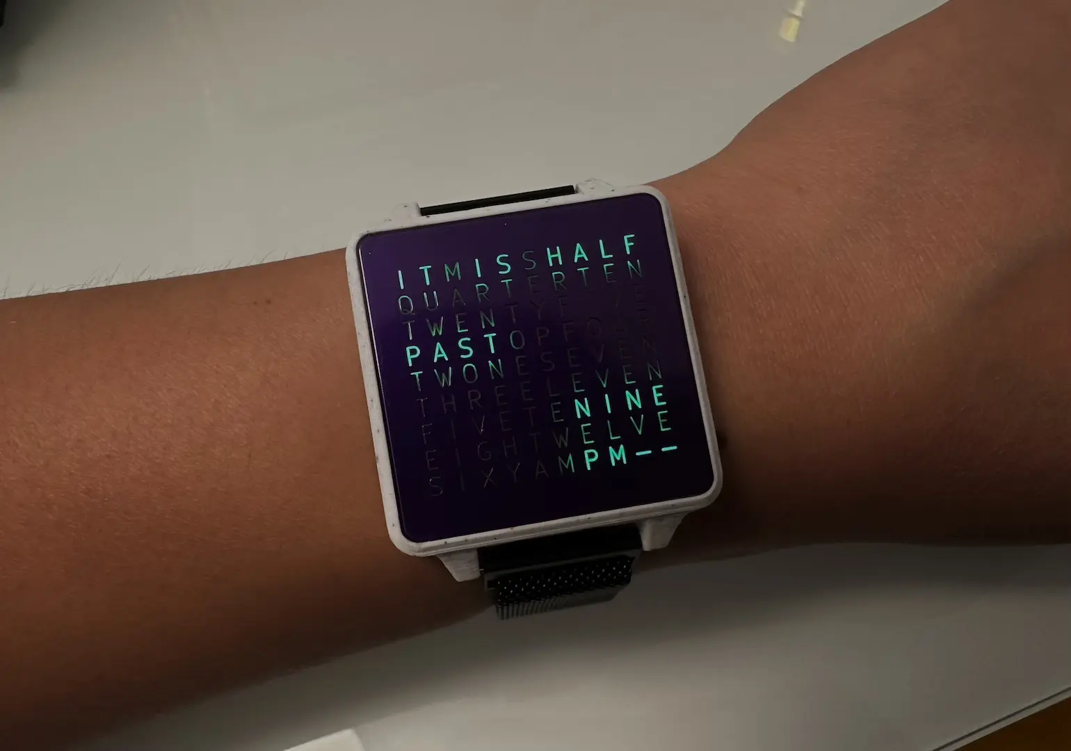
Overall the project works great. I do love pink so I made a pink version. However, my clothing style necessitated a black and white version.

Comments