
10BASE-T1L Converter w/ PoE+PoDL
miscboards/wch/adin1100_podl
kicadboards/breakouts/adin1100_podl
Recently I’ve been looking into the low-speed Ethernet variants, 10BASE-T1S and 10BASE-T1L. We’ll focus on 10BASE-T1L here. It offers 10Mbps full-duplex communication over 1km using a single twisted pair. The standard even supports PoDL which is like PoE but for SPE. Like my 100BASE-T1 Converter from a while ago, I decided to make a converter to normal Ethernet to start playing with 10BASE-T1L. For fun, I also added PoE and non-standard PoDL.
hardware
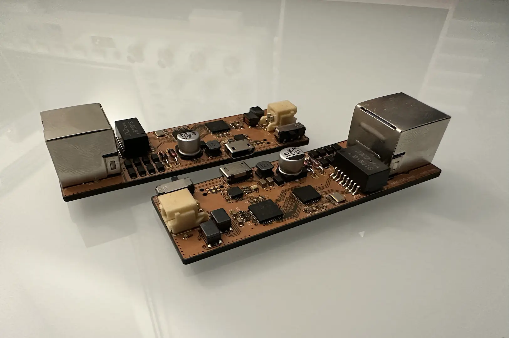
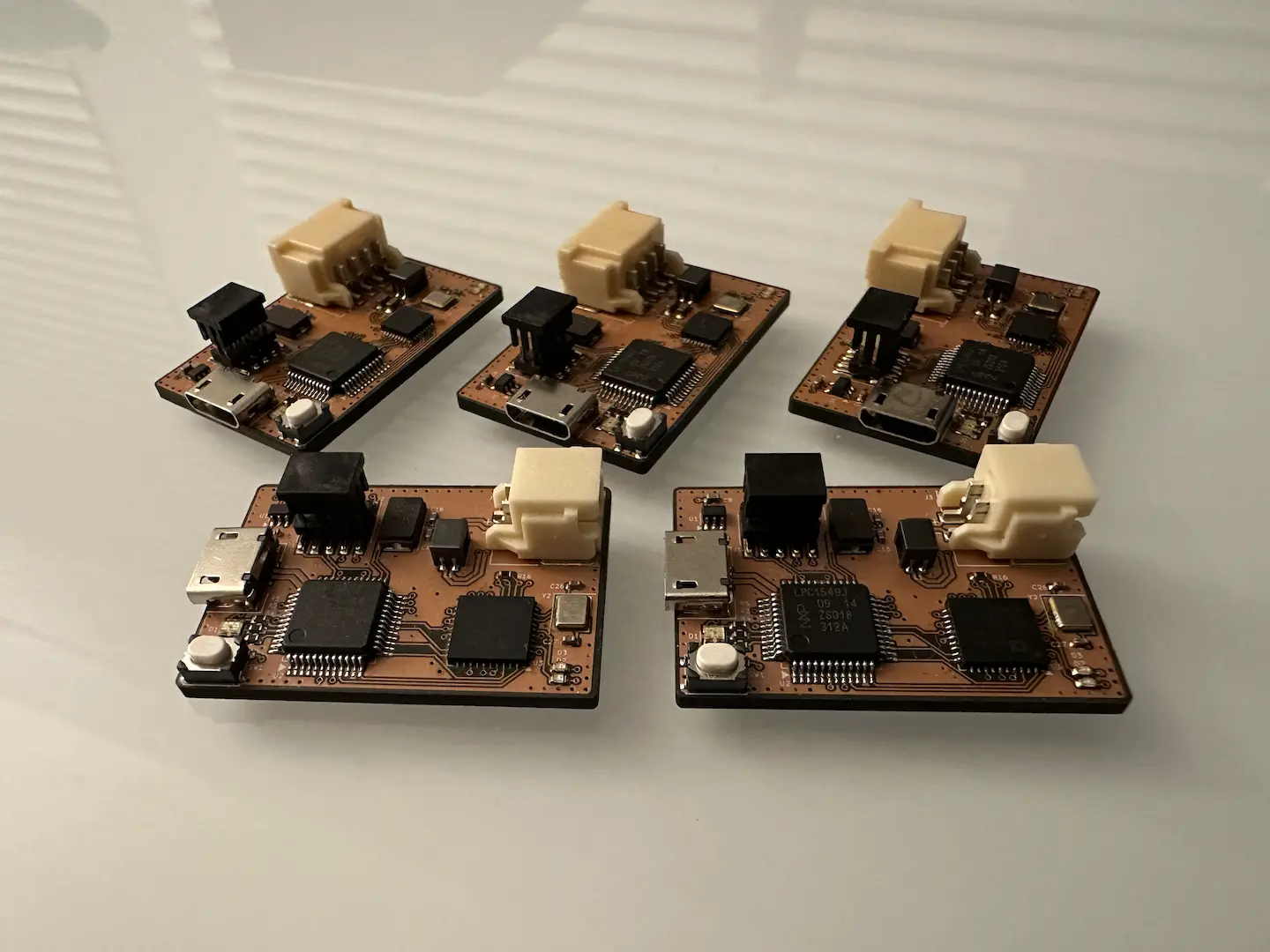
For the 10BASE-T to 10BASE-T1L conversion, I connected the RMII interfaces of the ADIN1100 and RTL8201F together. TXD0/1 go to the matching RXD0/1 and TX_EN goes to CRS_DV. I used the RTL8201F as the 50MHz clock source since it was easier. Importantly, since RMII multiplexes CRS and RX_DV onto CRS_DV, both PHYs need to be able to configure CRS_DV as RX_DV. Alternatively, the ADIN1100 supports a media converter mode which does something similar and requires no change to the RTL8201F. For MDIO configuration, I added the low-cost CH32V003. This meant I didn’t really need strapping resistors, but I added them anyway choosing sensible defaults.
For power, I started with the XDS TX4137 60V buck converter to supply 5V, or 4.5V actually due to my lack of good resistor values. Since the datasheet was in Chinese, I had to translate it and pray it worked. Thankfully, it did. Component size is always a compromise with rail noise, so I chose smaller components and used an LDO to drop to a stable 3.3V.
For PoE, I went with a discrete design I found online. All it does is present a 25kΩ load by default, turning on the real load above around 27V. This necessitated 2 full-bridge rectifiers and an idle power draw LED for the MPS, which increased board space. It’s not standards compliant since it’s not isolated, but it’s just for personal use so no worries.
For PoDL, I went with an “engineered” approach which just means not implementing the negotiation part. Conceptually, PoDL multiplexes the DC power on top of the AC signal using a large series inductance. Since the power circuit forms an RLC circuit, any load current spikes end up creating differential noise on the AC signal. Minimizing inductance and maximizing bulk capacitance helps, but this comes at size cost and too low an inductance will mess with the AC signal impedance and thus integrity. Since this generally only matters for 100mA level current spikes, I chose some standard values. From what I’ve seen, the standard PoDL circuit uses a common-mode choke (CMC) in front, piped into an isolation transformer for the AC signal and a differential-mode inductor (DMI) for the DC power. A DMI, which is a CMC connected differently, offers double the inductance due to mutual coupling and good matching to reduce conversion of common-mode to differential-mode noise. This comes at the cost of having no common-mode inductance which is why the CMC is required. While the isolation transformer is better for low-frequency noise, I only had capacitors on hand. Since this is engineered PoDL, once we’re past the inductors we just need a full-bridge rectifier to get the power out. To inject PoDL, I added a DPDT switch which shorts the full-bridge rectifier.
The layout was pretty fun and straightforward. I kept it about as small as I could get it and only on two layers. Not that it matters on this small board, but I made sure to length match and use the correct impedance differential pairs. Looking back, since RMII uses a single shared clock, it might be better to minimize trace lengths on signals going from clock follower to clock leader.
firmware
The firmware side was relatively simple. The bulk of the work was in the bitbanged MDIO driver. Since the last time I checked, the Linux driver I based my work on added clause 45 support to access an extended register space. This was particularly useful for configuring the ADIN1100. Configuration of the RTL8201F mainly involved forcing it to use 10BASE-T full-duplex only and making the LEDs do what I want. For the ADIN1100, I just needed to configure the LEDs since the defaults were good. 10BASE-T1L has autonegotiation which was nice, didn’t need to randomly select leader/follower roles and wait for a link up.
At the end of the day, the board worked perfectly!

Comments