
Getting Started With PetaLinux
After receiving the $20 EBAZ4205 in the mail, I decided to learn the basic process for getting a Linux image booted from the SD card. It runs a low-end Zynq SoC which is essentially an ARM microprocessor combined with an FPGA. While I am still a beginner in the world of embedded Linux and Zynq, I hope I can help others take their first steps.
Vivado
Everything starts with a Vivado project where we’ll configure options for the PS (Processing System) side containing the ARM processor and the PL (Programmable Logic) side containing the FPGA. From there, we can export to PetaLinux for Linux development or Vitis IDE for bare metal development. Let’s get started putting the block design together.
Minimum Requirements
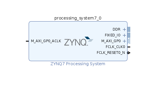
After creating the project – make sure to select “Project is an extensible Vitis platform” for easier exporting later – and selecting the right Zynq part, we need to add the PS to the block diagram.
According to UG1144, the bare minimum components needed to boot Linux on a Zynq-7000 are one TTC, >32 MB RAM, UART, and non-volatile memory (ex. QSPI, SD/MMC). The TTC can be enabled under “MIO Configuration > Application Processor Unit > Timer 0”. The RAM can be configured under “DDR Configuration > DDR Controller Configuration” where you can select among a bunch of known working parts and if not you can define your own. The UART and non-volatile memory can be enabled under “MIO Configuration > I/O Peripherals”. Much like a microcontroller, most of the peripherals can be remapped to other MIO. More interestingly, we can also remap peripherals to EMIO that can be mapped to pins controlled by the PL. It’s important to note that you can’t boot from a peripheral connected to EMIO since the PS side is what sets that up in the first place.
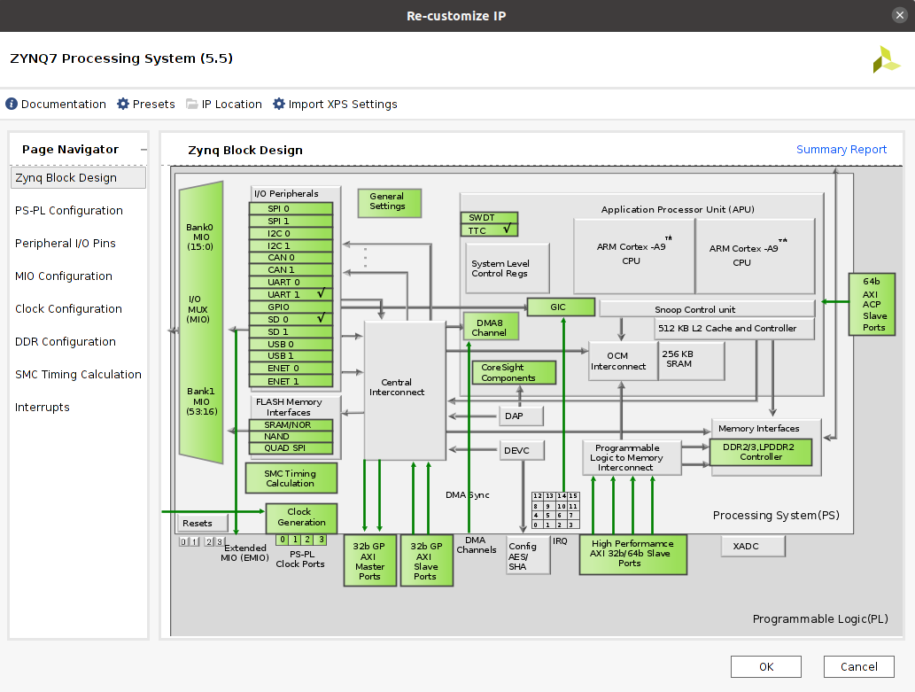
There’s a couple more things to set up. The input frequency can be configured under “Clock Configuration” but the default ended up being correct for me. You might also need to set the correct voltage standard for IO banks under “MIO Configuration”.
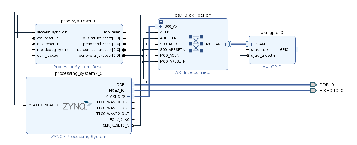
A “Processor System Reset” block is also required along with referencing it in the “Platform Setup > Clock” tab. A master AXI port also needs to be selected under “Platform Setup > AXI Port” along with its clock connected. An AXI device needs to be connected or else we get a “failed to find amba_pl node” error later due to some device tree errors, so I added an “AXI GPIO” block and ran connection automation to hook it up. Thankfully, Vivado’s “Run Connection Automation…” is pretty good and will connect most things correctly.
EBAZ4205 Ethernet
The EBAZ4205 maps all of the MII pins through EMIO so we’ll need to do that next. We start by enabling ENET 0 and the associated MDIO under “MIO Configuration > I/O Peripherals” and change its IO to EMIO. Since the EBAZ4205’s PHY is only 100 Mbps, we’ll need to configure that under “Clock Configuration > IO Peripheral Clocks”. Then we need to make the GMII and MDIO pins external in the block design. Since we’re using MII and not GMII, we don’t actually need all the pins in the GMII harness, but I was lazy and made it all external.
The EBAZ4205 I received didn’t have the PHY crystal soldered and instead sourced it from one of the PS PLLs. The PHY it uses requires a 25MHz clock, so we can configure that under “Clock Configuration > PL Fabric Clocks” and then make the corresponding pin external.
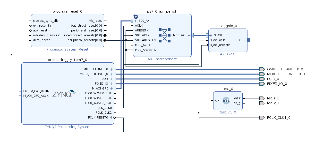
Finally, we can map all the EMIO to the correct pins in an XDC file. For some reason, Vivado doesn’t allow you to leave pins as a no connect so we have to map all those unused GMII pins to somewhere. One interesting gotcha I ran into was that initially all of my received Ethernet packets came in as error because I didn’t have a pulldown on the RX_ER signal.
Export to PetaLinux
Finally, we can save our block design and run “Create HDL Wrapper…” to generate the top level HDL file. From there we can run “Generate Bitstream…” to generate the bitstream that we’ll load at boot. Finally, we can run “File > Export > Export Platform…” (make sure to include bitstream) and generate the XSA file we can import into PetaLinux.
PetaLinux
Most places tell you to install PetaLinux using the normal installer, but I just used Xilinx’s Unified Installer which has the added benefit of being easily managed along with my Vivado installation. Don’t forget to source the settings64.sh file before starting to call your PetaLinux commands (I added it to my .bashrc). Let’s start by making a PetaLinux project.
petalinux-create --type project --template zynq --name <proj folder name>
petalinux-config --get-hw-description <path to XSA>
Then we can configure things like kernel options, U-Boot options, Yocto recipes, etc.
petalinux-config # PetaLinux settings
petalinux-config -c kernel # kernel options
petalinux-config -c rootfs # packages
petalinux-config -c uboot # U-Boot options
petalinux-config -c busybox # BusyBox options
# there's probably more these are the ones I found
The options that I changed from the default were using an EXT4 root filesystem and adding SD boot option to U-Boot.
Finally we can compile our image!
petalinux-buildThen we need to package a boot.bin which is what the Zynq boot ROM searches for and initially loads from the SD card (boot strap pins can change the default boot source). boot.bin contains the FSBL which loads the optional bitstream and U-Boot SPL which finally boots Linux.
petalinux-package --boot --fsbl ./images/linux/zynq_fsbl.elf --fpga ./images/linux/system.bit --u-boot --forceNext we need to create a FAT boot partition and EXT4 partition for our filesystem on our SD card. I use GParted. Copy over the BOOT.BIN, boot.scr, and uImage (image.ub doesn’t work for me for some reason) from the images/linux folder into the boot partition. Extract the the root filesystem over to the EXT4 partition.
sudo tar xvf ./images/linux/rootfs.tar.gz -C <path to mounted ext4 partition>Finally we can load the SD card and test everything!
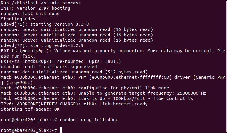
Extra
For fun, let’s reuse the NAND flash onboard as UBIFS storage by following https://www.xilinx.com/support/answers/69765.html. First we need to enable the NAND peripheral in Vivado. Then we can follow the instructions in the link to enable kernel support and install UBIFS utils. Rebuild everything and install on the SD card. Finally, there’s a couple of commands to format the flash as UBIFS and make a new volume.
Comments