
CalState LA Internship
Written 9-1-19
As a requirement for the TroyTech program, we had to do an internship during the summer after junior year. I ended up doing my internship at CalState LA with Professor Shen. Among the various tasks he presented me, I chose to work on a low-cost, lightweight robot arm for a teleoperation robot he and a couple students were working on.
In the interest of time, I will gloss over many of the details that went into the arm, especially the iteration and testing process. I will more or less summarize the result of my work and a basic narrative. Ok, I already do this with most of my posts, but this one especially because my draft is looking way too long.
Design Requirements
Before even starting to work on the robot arm, I did a bunch of research into existing robot arms on the market, looking into factors like cost, size, strength, weight, etc. One company in particular, Kinova, built a robot arm that pretty much satisfied every requirement we were going for, except it cost over $20k which was way outside our budget. Still, the specifications of their robot arms served as the basis for a couple of design goals for my robot arm. Here’s the basic requirements I laid out:
- Cost: ~$2k
- Weight: <3kg
- Reach: >800mm
- Joint speed: 8rpm
- Carrying Capacity (at max extension): 0.5kg
- 7DOF (later reduced to 5DOF)
- Go from scratch to finished product in 8 weeks
Brainstorming
In order to simplify the process and improve modularity, I decided to create general purpose joints. The joint had to be able to handle the maximum load which was at full extension parallel to the ground with a 0.5kg weight at the end. Doing some rough calculations and estimations of weight distribution, I found that, including a safety factor, this general purpose joint would have to handle 20 Nm of torque.
For a motor, I ended up using an off the shelf hobby brushless motor. Balancing specifications like Kv, weight, and power to ensure I would still meet my requirements, I chose ~1000Kv motors of about 3542 size if I remember correctly.
For the gearbox, I needed high stiffness, high load, and low backlash. This necessitated something like a strain wave gearbox, but since those are quite expensive, I decided to design my own.
Inspired by Haddington Dynamic’s Dexter robot arm whose sine wave encoders achieve arbitrary precision, I decided to design my own too. I originally wanted to build the Dexter arm, but back in the day not enough files were released despite it being an open source project.
Making the Gearbox
Based on my motor choice and the lead acid battery we were using, the gearbox needed to have a 1:900 reduction. This is quite high, even for a strain wave gearbox. Handling 20Nm in a relatively compact package was also no easy task. Here’s an explanation of how strain wave gearing works.
In order to get output from the flexspline, the standard implementation is to use a cup attached to the flexspline. However, this results in a very thick gearbox. Doing more research, I found out about Harmonic Drive’s pancake gears which were exceptionally thin. Once I understood the design, I immediately got to trying to get it 3D printed.
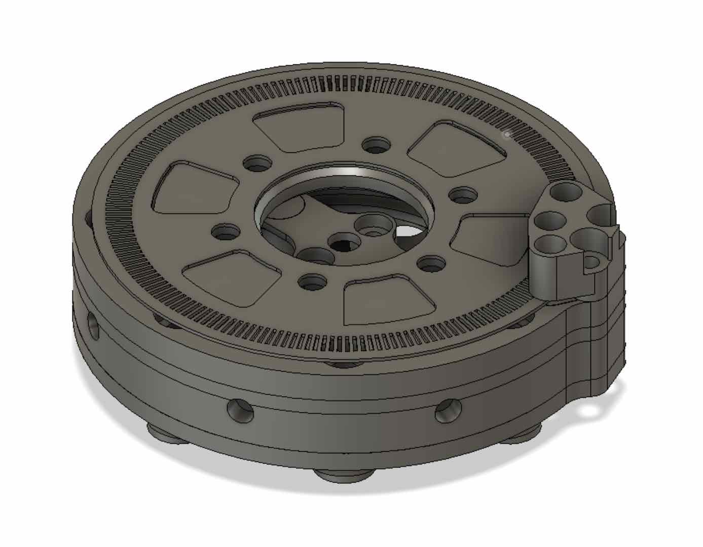
I somehow didn’t get any close up pictures, but it did work perfectly. Next I moved onto making the 1:900 gearbox, which is where multiple challenges showed up, included gear tooth strength, material stiffness, and noise. I used two 1:30 stages to get the 1:900 gear ratio.
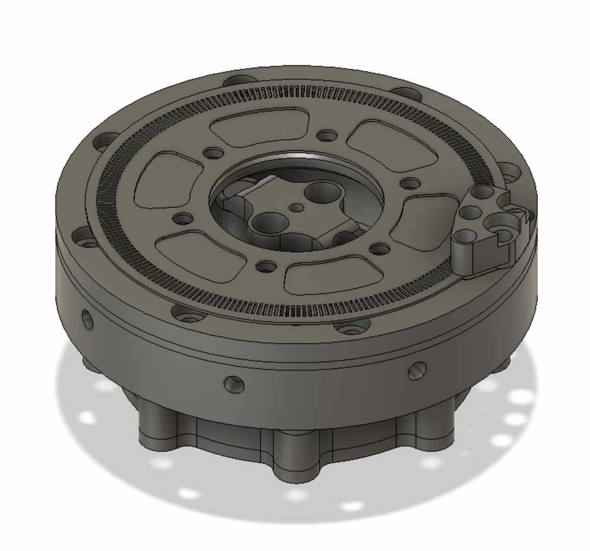
I also somehow didn’t get any close up pictures of this, but after quite a bit of testing and iteration I had a gearbox that I was satisfied with.
To sum it up, after 6 weeks of development, I finally had a 3D printed 1:900 dual stage strain wave gearbox capable of a 20Nm load, which was something that didn’t exist yet as far as I knew.
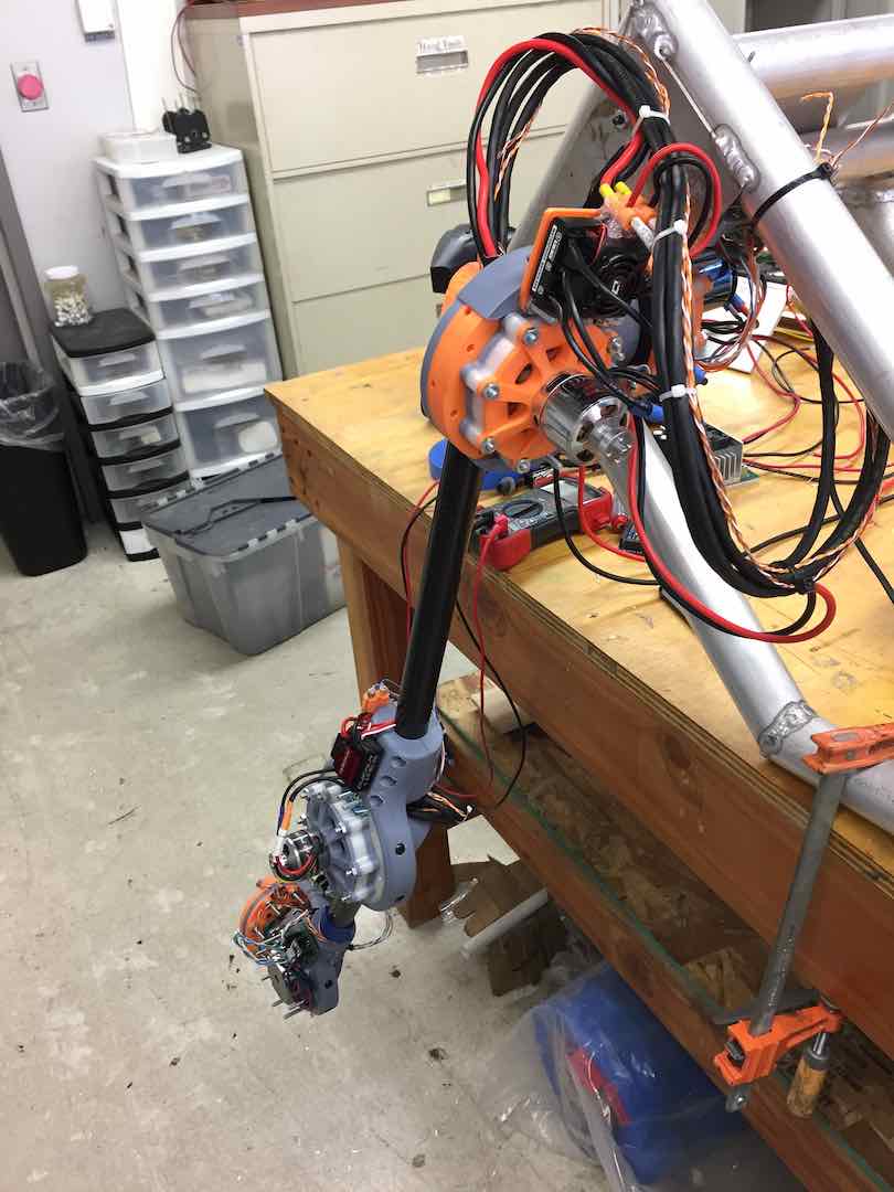
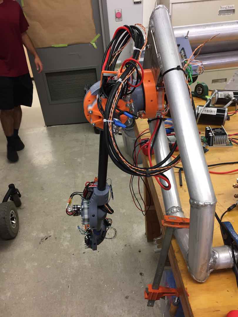
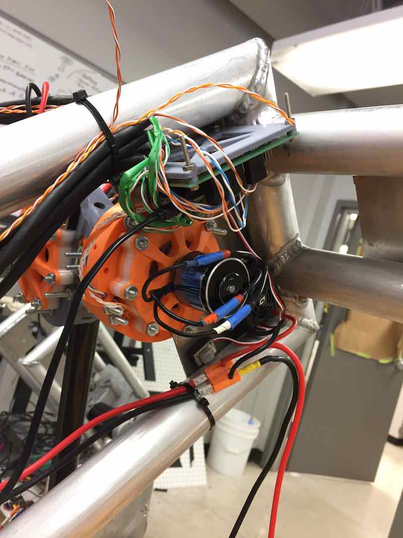
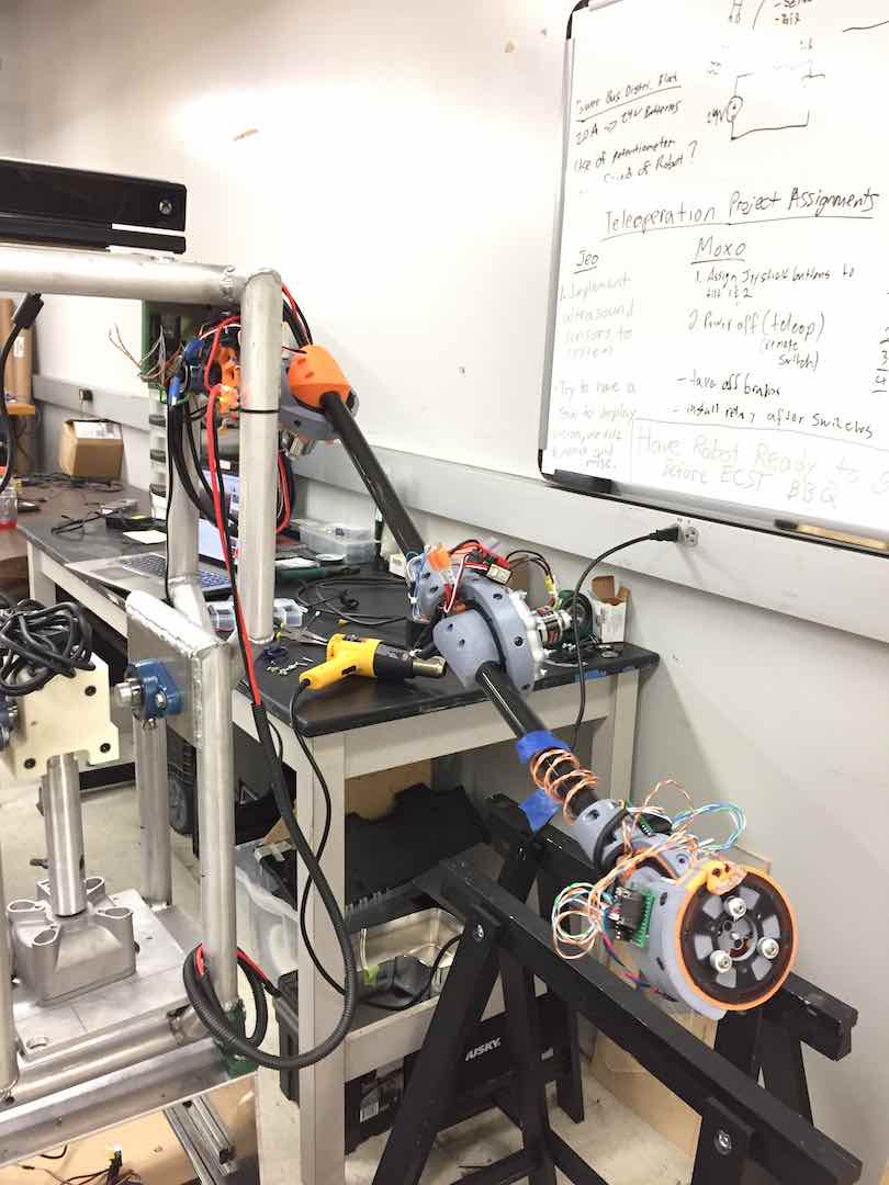
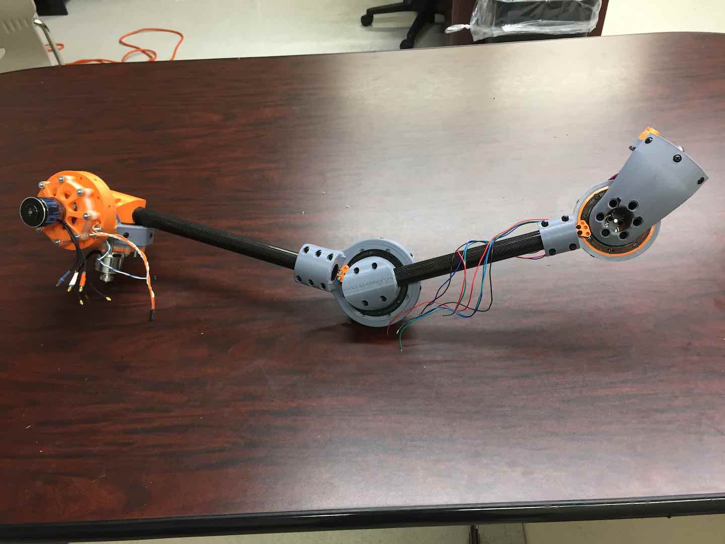
Putting the Arm Together
With the general purpose joint done, I got onto assembling a couple of them together into a robot arm. Because of weight, I used 1:50 gearboxes with stepper motors for the wrist joints. I really liked how I routed all of the wiring through the carbon fiber tubes that made up the arms. After designing a couple of mounts, I got to printing and assembly.
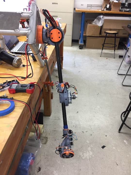
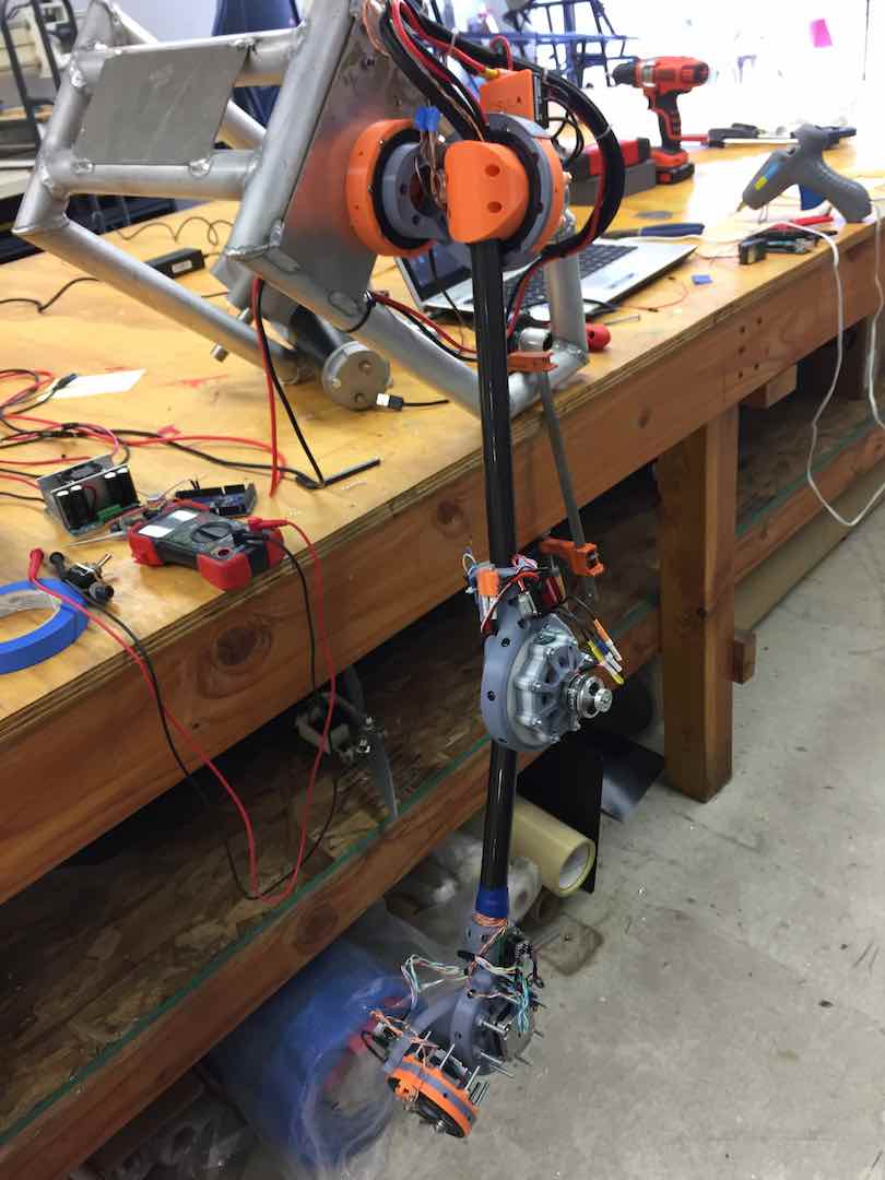
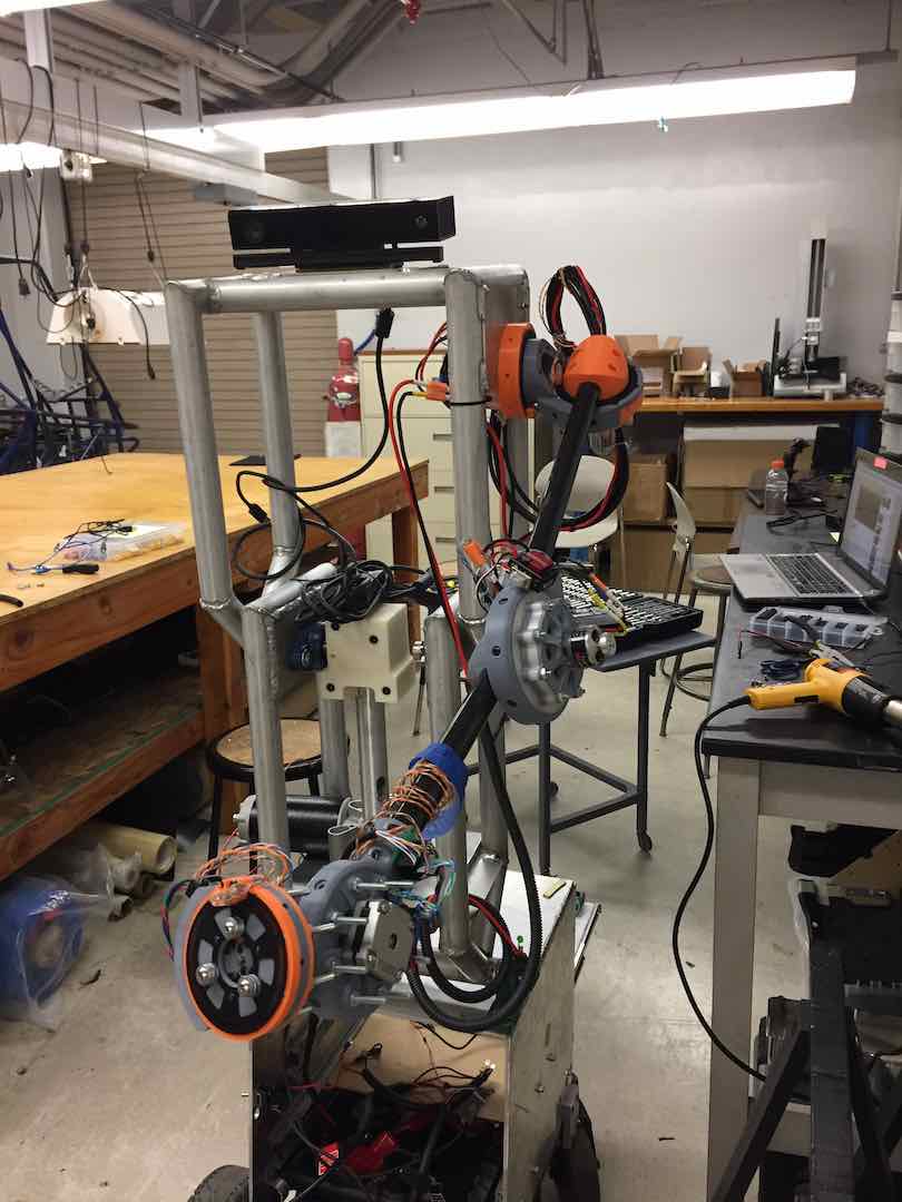
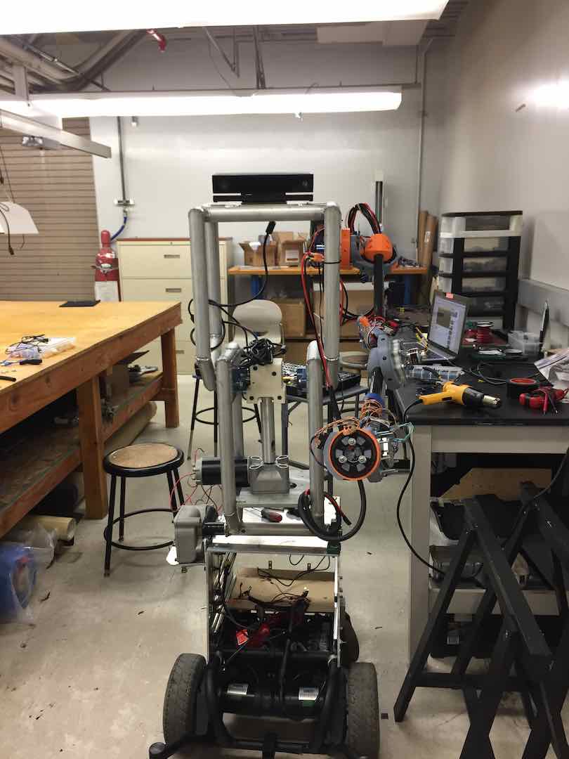
Before I knew it, my 8 weeks were up and I had to head back to high school. I only barely finished assembling the arm and the electronics. The code wasn’t even near completion. Still, I left behind enough documentation and files so that other students could pick up the project. In fact, over a year later I found out that they had replicated my robot arm!
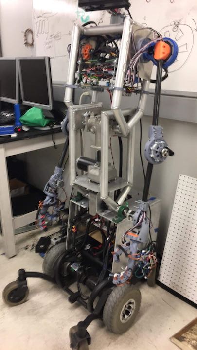
I didn’t think my arm was particularly well designed, so I was pretty flattered that it was good enough to replicate and continue working on.

Comments